
Blade Application Guides
Browse focused application knowledge
Cutting guides by industry, process, equipment and defect
Use these curated topic pages to compare related materials and cutting conditions without relying on broad site search.
Industries
Cutting processes
Equipment types
Cutting defects
Technical Articles
Industrial cutting problem knowledge base
1857 Blade Application Guides
Search by material, industry, cutting process or a problem described in your own words. You do not need to know the exact blade name.
Films & Foils
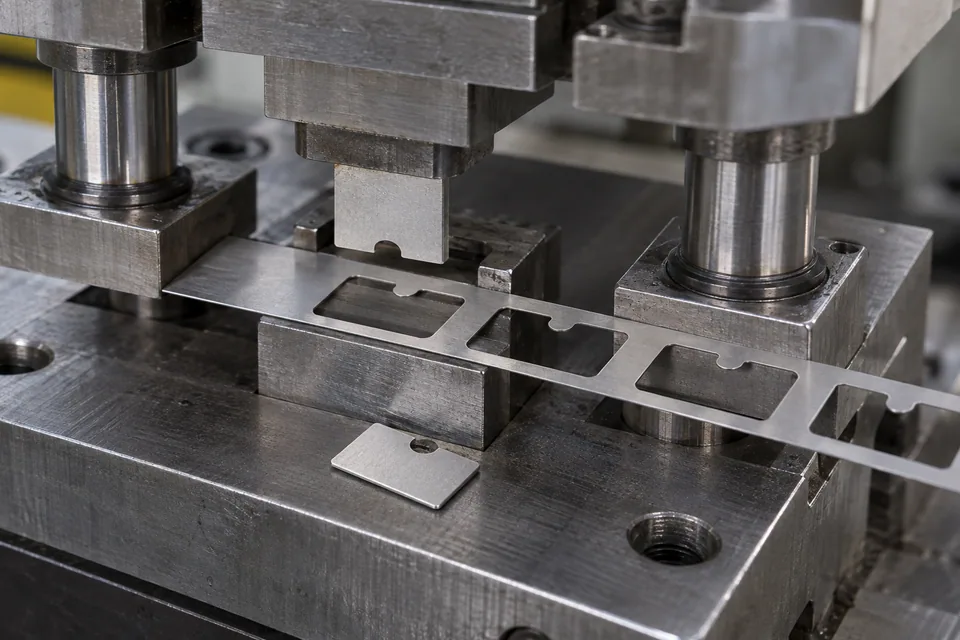
Tantalum Metal Foil Precision Blanking Blades
Blank drawing-defined tantalum foil pieces with a matched punch and die while controlling burr, slug release and surface condition.
Read the application guide →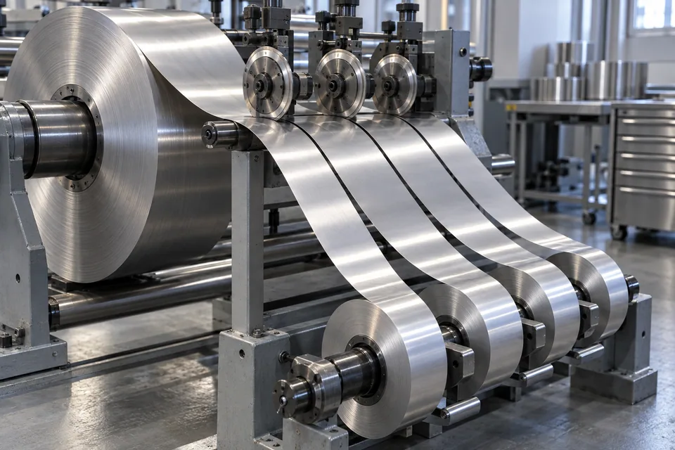
Films & Foils
Niobium Metal Foil Precision Coil Slitting Blades
Slit approved niobium foil coils into stable narrow rolls while checking edge burr, camber and grade identity.
Read the application guide →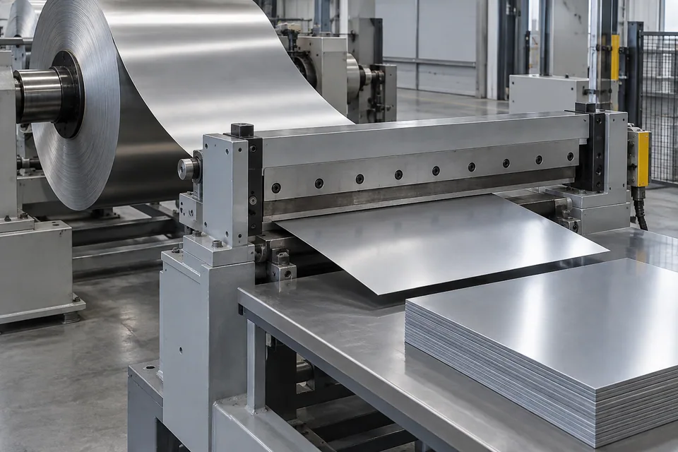
Films & Foils
Niobium Metal Foil Cut-To-Length Blades
Crosscut niobium foil coil into finite rectangular blanks with controlled squareness and edge quality.
Read the application guide →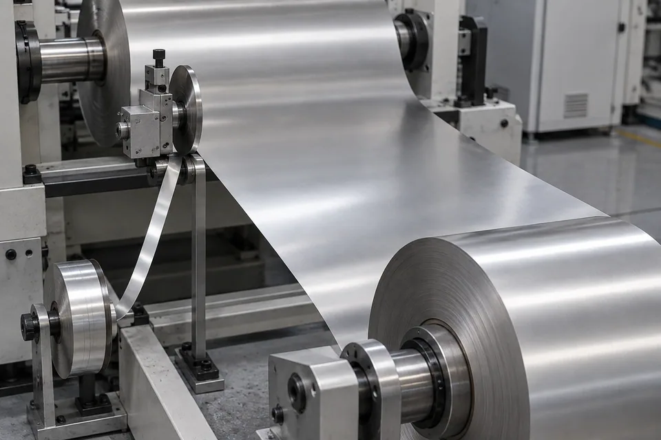
Films & Foils
Niobium Metal Foil Strip Edge-Trimming Blades
Remove a narrowly approved outside margin from niobium foil strip without sacrificing required usable width.
Read the application guide →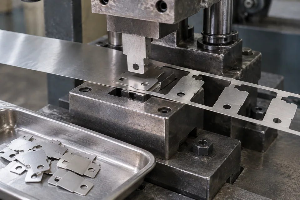
Films & Foils
Niobium Metal Foil Precision Blanking Blades
Punch drawing-defined niobium foil preforms while controlling burr, flatness, slug release and later draw behavior.
Read the application guide →
Films & Foils
Rolled-Annealed Copper Foil Precision Coil Slitting Blades
Plan longitudinal slitting of rolled-annealed copper foil for flexible electronics with surface, burr and rewind checks.
Read the application guide →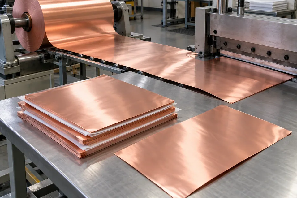
Films & Foils
Rolled-Annealed Copper Foil Cut-to-Length Blades
Crosscut bare RA copper foil rolls into flat sheets while protecting surface, squareness and handling integrity.
Read the application guide →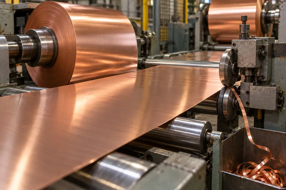
Films & Foils
Rolled-Annealed Copper Foil Strip Edge-Trimming Blades
Remove only a documented damaged outer margin from RA copper foil while preserving laminate-ready width and face.
Read the application guide →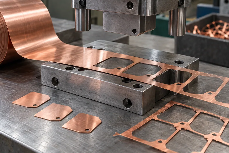
Films & Foils
Rolled-Annealed Copper Foil Precision Blanking Blades
Trial die blanking for approved RA copper foil shield contours with part support, burr and electrical handoff checks.
Read the application guide →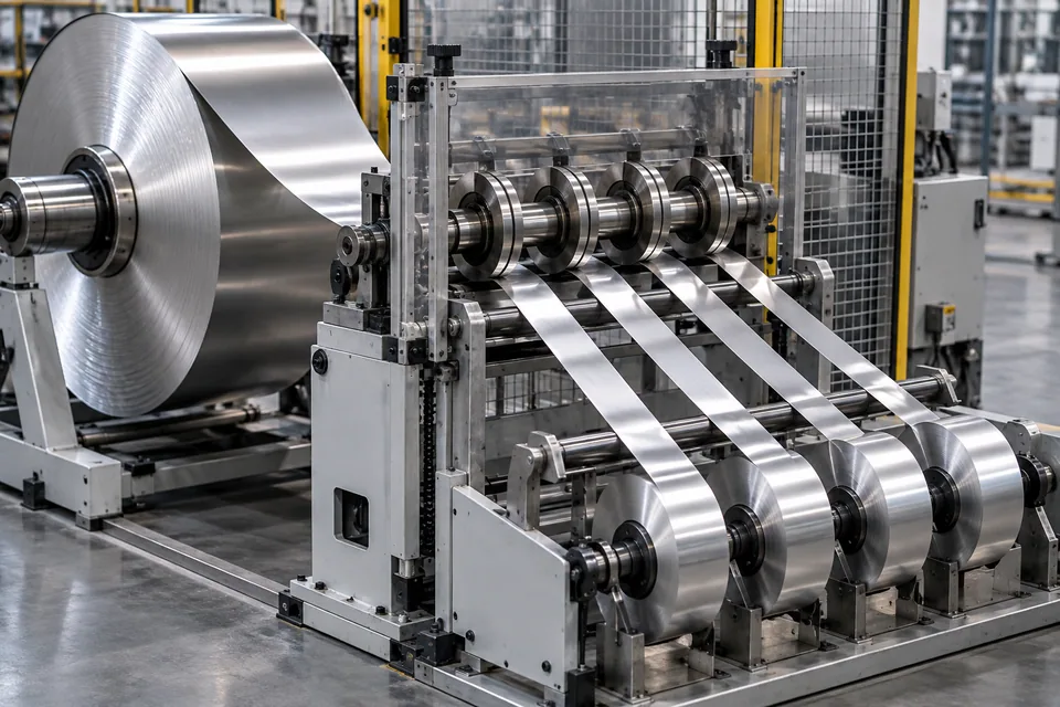
Films & Foils
Ultra-Thin Stainless-Steel Foil Precision Coil Slitting Blades
Slit ultra-thin stainless foil coils into narrow electronic-material lanes with grade, temper, burr and winding controls.
Read the application guide →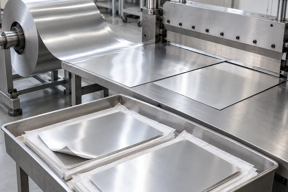
Films & Foils
Ultra-Thin Stainless-Steel Foil Cut-to-Length Blades
Crosscut ultrathin stainless foil into flat blanks with squareness, curl, scratch and packaging checks.
Read the application guide →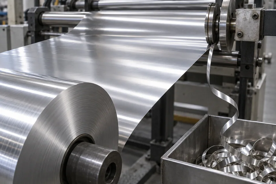
Films & Foils
Ultra-Thin Stainless-Steel Foil Strip Edge-Trimming Blades
Remove an approved narrow outer margin from ultrathin stainless foil without sacrificing useful width or flatness.
Read the application guide →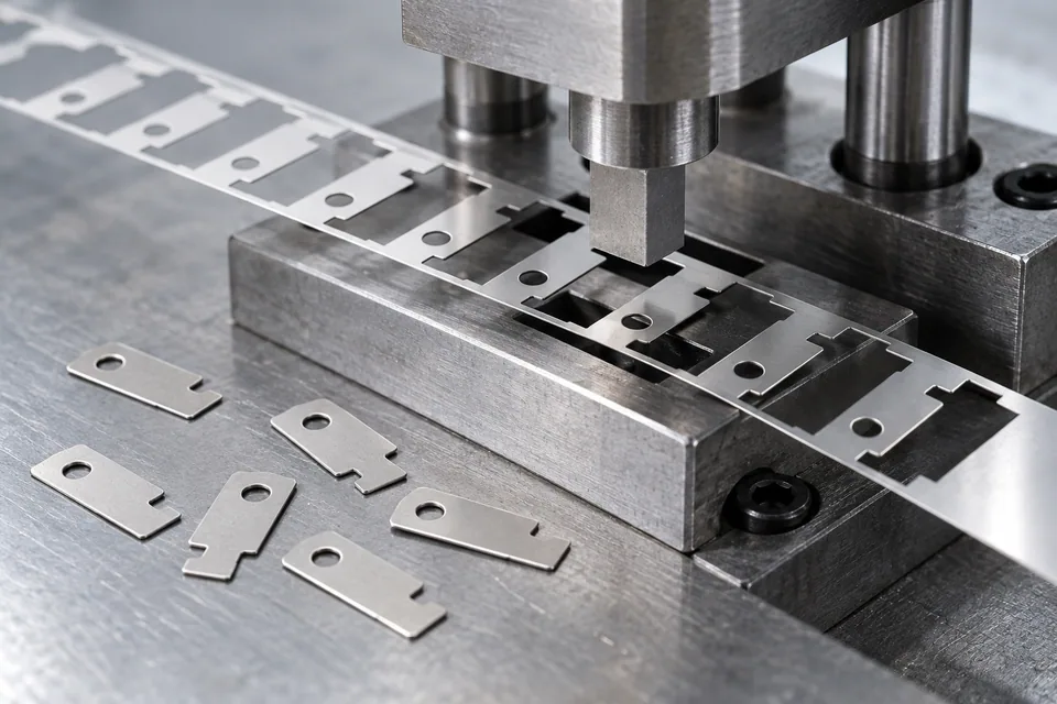
Films & Foils
Ultra-Thin Stainless-Steel Foil Precision Blanking Blades
Assess punch-and-die blanking of ultrathin stainless foil for drawing-defined small parts with burr and slug controls.
Read the application guide →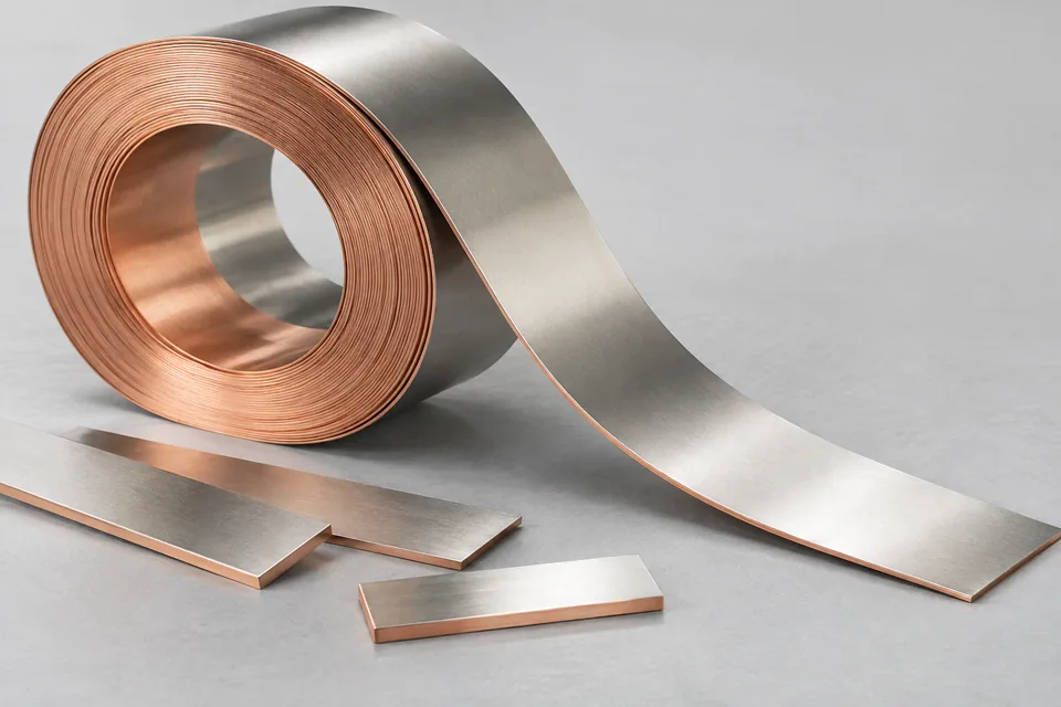
Metals, Coils & Strips
Nickel-Clad Copper Strip Precision Coil Slitting Blades
Slit metallurgically clad nickel/copper strip into battery-lead lanes while checking exposed copper edge, bond and burr.
Read the application guide →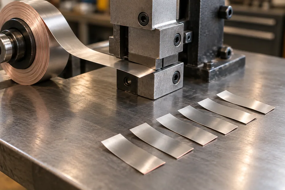
Metals, Coils & Strips
Nickel-Clad Copper Strip Cut-to-Length Blades
Crosscut Ni/Cu clad strip into straight battery-lead blanks with cross-section, end burr and joining-surface checks.
Read the application guide →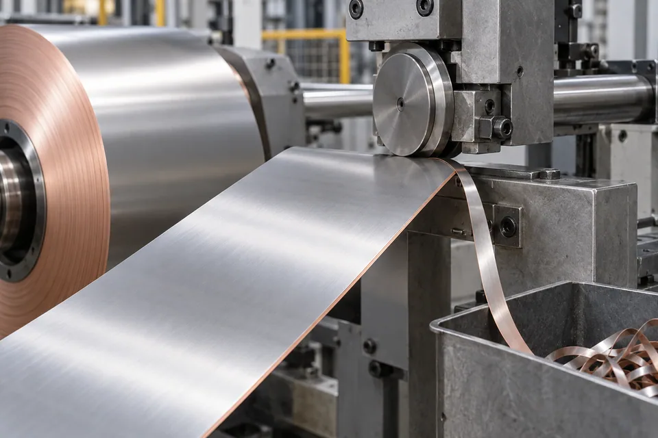
Metals, Coils & Strips
Nickel-Clad Copper Strip Edge-Trimming Blades
Evaluate a conditional single-edge trim on nickel-clad copper strip while checking exposed copper, layer lift and retained width.
Read the application guide →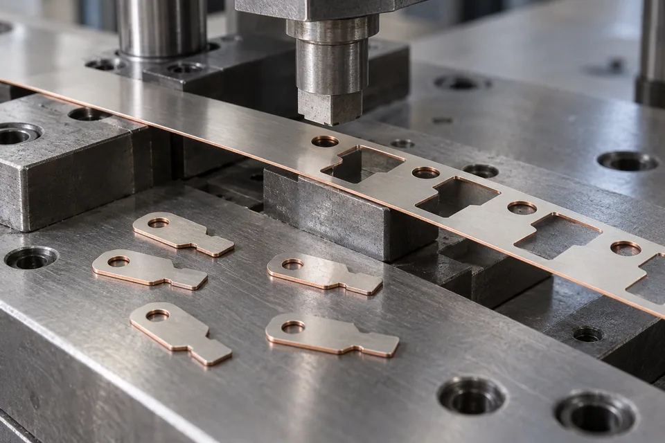
Adhesives, Labels & Printing
Nickel-Clad Copper Strip Precision Blanking Blades
Assess punch-and-die contour blanks in bonded nickel-copper strip without assuming a plated strip behaves the same way.
Read the application guide →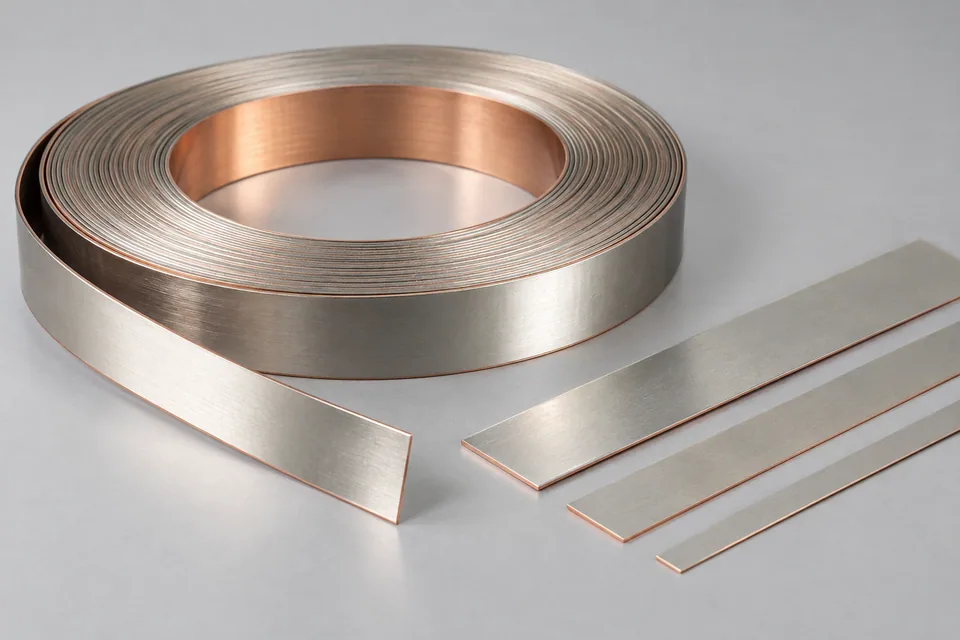
Metals, Coils & Strips
Tin-Plated Copper Strip Precision Coil Slitting Blades
Plan longitudinal slitting of tin-plated copper strip into connector-feed coils with coating and burr checks.
Read the application guide →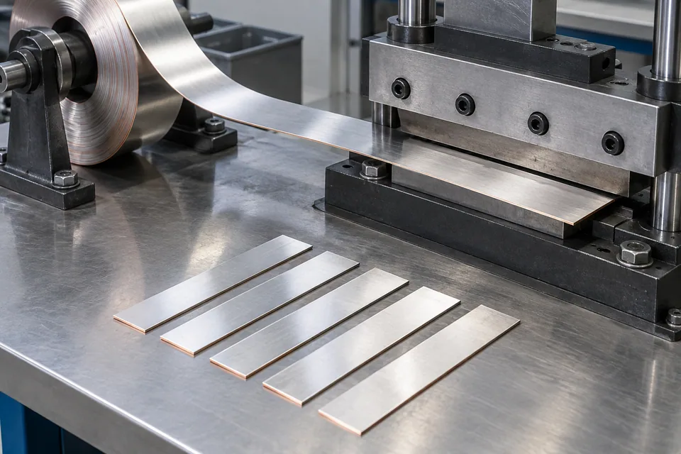
Metals, Coils & Strips
Tin-Plated Copper Strip Cut-to-Length Blades
Crosscut a specified tin-plated copper coil into flat rectangular blanks while preserving plating faces and cut-end quality.
Read the application guide →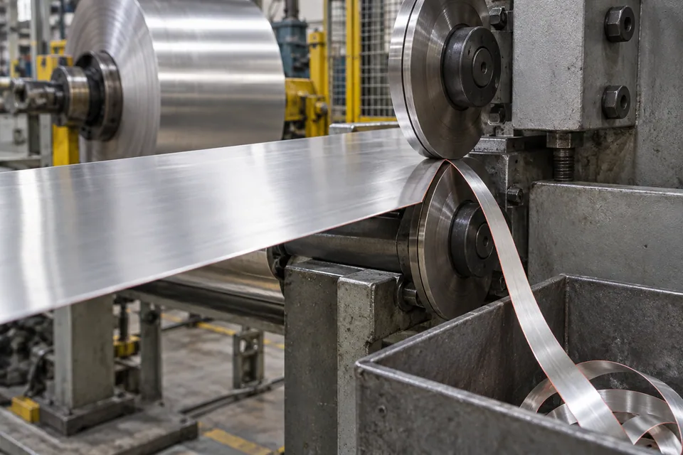
Recycling & Size Reduction
Tin-Plated Copper Strip Edge-Trimming Blades
Evaluate a one-sided edge trim only where a plated copper strip has a documented damaged margin or revised usable width.
Read the application guide →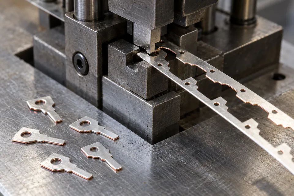
Recycling & Size Reduction
Tin-Plated Copper Strip Precision Blanking Blades
Trial punch-and-die terminal profiles from tin-plated copper strip with coating, slug and burr inspection.
Read the application guide →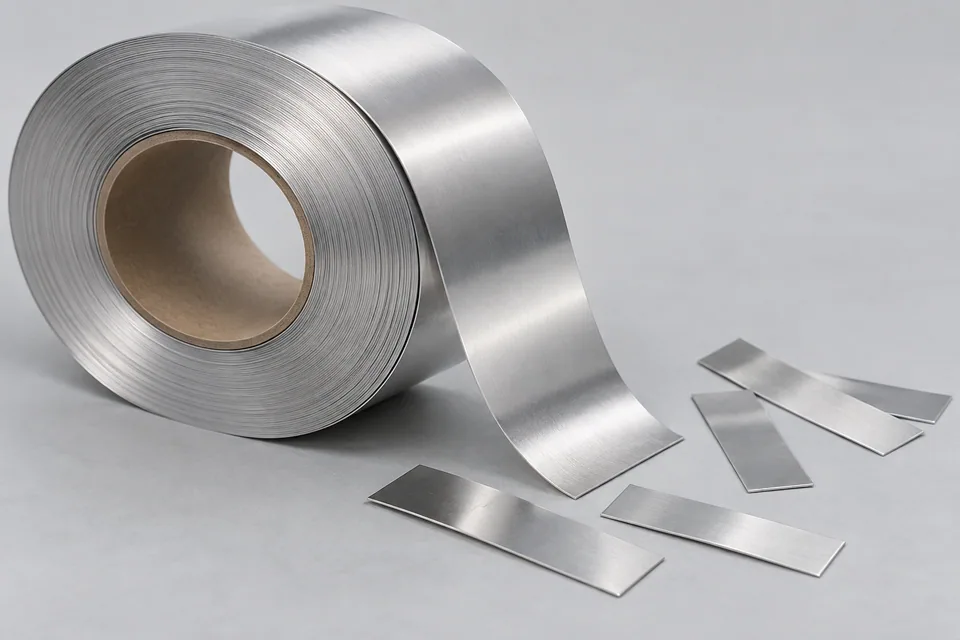
Films & Foils
Aluminum Battery-Tab Stock Precision Coil Slitting Blades
Evaluate longitudinal slitting of clean aluminum cathode-lead foil into narrow tab-stock coils.
Read the application guide →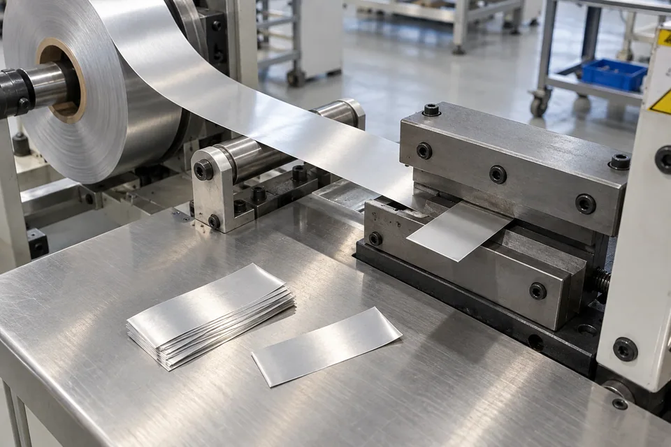
Metals, Coils & Strips
Aluminum Battery-Tab Stock Cut-to-Length Blades
Plan straight transverse cuts from aluminum cathode-lead strip into flat tab lengths. Provide flat aluminum lead lengths to the released drawing.
Read the application guide →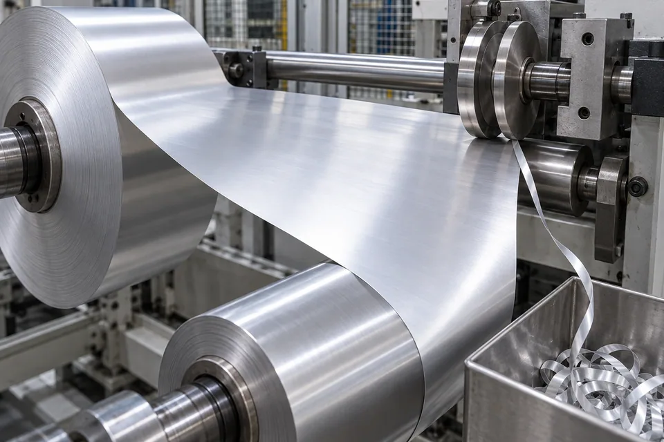
Films & Foils
Aluminum Battery-Tab Stock Strip Edge-Trimming Blades
Use a conditional one-sided trim to remove a documented damaged margin from uncoated aluminum lead-stock strip.
Read the application guide →Industrial Blade Application Guides: From Material to Cutting Edge
Reliable cutting comes from a system, not a single hardness number. Industrial blade technology connects the processed material, cutting method, machine condition, blade material, heat treatment, geometry, grinding accuracy and maintenance practice.
This page gives engineers and buyers a practical framework for discussing blade performance with Meirente before a quotation, trial or repeat-order improvement.
Start With the Cutting Application
A thin film, abrasive glass fiber, soft food product, polymer strand and electronic ceramic sheet place very different demands on a blade. The first questions should cover material behavior, thickness, speed, cutting gap, temperature, contamination, target finish and the cost of downtime.
Material Selection Is a Balance
Tool steel, stainless steel, high-speed steel, powder-metallurgy grades, tungsten carbide and coated solutions offer different combinations of hardness, toughness, wear resistance, corrosion resistance and cost. Selection should reflect the dominant failure risk instead of using the same grade for every application.
Edge Geometry Controls How the Blade Enters the Material
Bevel angle, single- or double-bevel direction, edge thickness, tooth pitch, tooth height, rake and clearance influence cutting force, dust, burrs, heat and edge strength. A sharper edge can reduce force, but an edge that is too thin may chip or deform under impact.
Heat Treatment, Grinding and Surface Engineering
Heat treatment develops the material properties required by the design. Precision grinding then controls flatness, parallelism, runout, concentricity and final edge geometry. Surface finishing or coating may help with wear, friction, corrosion or material adhesion when the application and base material justify it.
Measurement and Failure Feedback
Inspection confirms whether the blade matches the agreed specification; production feedback confirms whether the specification matches the real process. Photos and records of wear, chipping, deformation, burrs, dust, motor load, heat and cutting hours help separate material problems from alignment, gap, vibration or contamination issues.
Is higher hardness always better?
No. Higher hardness can improve wear resistance but may reduce toughness. The correct balance depends on impact, material abrasiveness and machine stability.
Why does the same blade wear differently on two machines?
Alignment, holder condition, cutting gap, speed, cooling, vibration, contamination and processed material can all change blade life.
When should a coating be considered?
Consider it when wear, friction, corrosion or adhesion is a defined problem and the coating is compatible with the base material, edge and operating temperature.
What information helps diagnose chipping?
Provide the chipped location, installation direction, holder condition, cutting gap, speed, processed material, contamination risk and close-up photos.
Can edge geometry be changed without changing the machine?
Sometimes, but the blade-holder interface, clearance and cutting method must be reviewed before any geometry change is approved.