
Blade Application Guides / Application Guide / Electronic metal converting
Rolled-Annealed Copper Foil Precision Blanking Blades
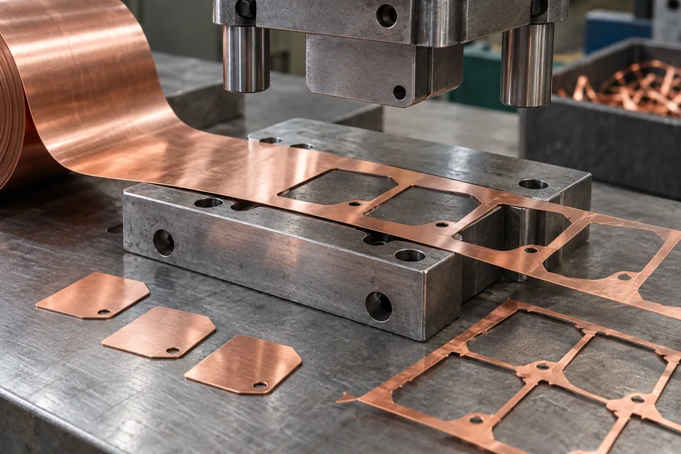
Tex Technology documents rolled-annealed copper foil as a flexible conductor stock. Takachi shows custom-shaped rolled copper foil shielding pieces and notes that a cutting die can be used for mass production; PPI documents die-cut copper shapes for transformer shields and insulated winding laminates. These sources support shaped copper-foil parts, but do not mean an FPC conductor pattern is normally punched out of bare RA foil. This guide is limited to a buyer-approved discrete shield, ground-contact or similar contour where a punch-and-die route is specified. The converter must also confirm whether the supplied workpiece is truly bare RA foil or a rolled-copper adhesive laminate; Takachi’s example includes adhesive and paper liner. The layer stack changes how the die is set and how pieces are removed.
Updated
Where This Cutting Application Appears
Confirm the target part and its layer stack
Collect the actual shield or contact drawing with holes, tabs, keep-out features and placement orientation. Identify bare copper versus adhesive-backed copper with liner. An FPC design with etched fine traces belongs to a different manufacturing route; a die trial should not imply that blade-cut trace resolution is equivalent.
Support the thin foil at die entry
Trial the selected RA temper on a restrained web or carrier. Set punch registration and ejection so narrow copper bridges do not fold or remain in the skeleton. Inspect upper and lower cut faces; a burr toward a contact surface can interfere with placement or make a sharp handling edge.
Inspect the part and surrounding scrap
Measure contour, hole position and flatness after release. Look for necking at corners, metal slivers, curled tabs and die scratches. Verify slugs and skeletal scrap are removed without dragging over the useful face or contaminating an adhesive layer if one exists.
Test the receiving shield geometry
Package parts with face and rolling-direction identification. The buyer must fit them to the housing or ground feature and verify continuity, shielding and bonding by its own procedure. A clean outline cannot certify circuit or enclosure performance.
Define the Required Cut Result
- Produce drawing-defined foil contours with intact narrow features.
- Limit burrs, slugs and metal fragments.
- Preserve copper face and optional liner integrity.
- Keep die-cut parts flat for assembly.
Problems to Diagnose Before Changing the Knife
A narrow copper tab tears
- Review die support and ejection.
- Inspect RA temper and punch edge wear.
Burr points toward the bond surface
- Compare punch direction and die clearance.
- Inspect both faces on early and late samples.
Small slugs remain on parts
- Review matrix takeoff and static behavior.
- Inspect trays and adhesive face if present.
Knife Forms That May Be Considered
| Possible knife form | When it may be considered | What must be confirmed |
|---|---|---|
| Matched punch-and-die set | For a released discrete shield or contact contour. | Confirm tab integrity, burr, geometry and scrap removal. |
Information to Send for Technical Review
You do not need to know the exact blade name. Send the available workpiece, machine, current-knife and cut-result information so the application can be reviewed against a drawing or sample.
- RA foil alloy, temper and thickness
- Bare foil or adhesive/liner layer stack
- Released contour, holes and contact direction
- Die support, clearance and ejection plan
- Allowed burr, curl and scratch samples
- Scrap and slug removal method
- Part packaging and face orientation
- Assembly-level continuity and shielding tests
Questions About This Cutting Application
Is this a way to fabricate fine FPC traces?
No. It concerns discrete contours; FPC conductor patterns use the buyer’s qualified circuit process.
Does the Takachi example prove bare-foil cutting?
It shows rolled copper with adhesive and liner; bare stock needs a separate trial.
Why inspect slugs?
A loose copper slug can contaminate a useful part or contact.
Can a dimensionally correct shield still fail?
Yes. Fit and electrical performance belong to the assembled design.
What belongs in the first RFQ?
Send the complete stack, RA foil grade and released contour drawing.
Public references and scope
These public sources provide material, cutting-method or safety context for this guide. Supplier pages describe their own materials or equipment; they do not establish a MEIRENTE blade specification or performance claim. Confirm the actual grade, machine setup and required cut with a drawing or sample.
Related product and service information
- Rolled-Annealed Copper Foil Precision Coil Slitting Blades - rolled-annealed copper foil · precision coil slitting
- Ultra-Thin Stainless-Steel Foil Precision Blanking Blades - ultra-thin stainless-steel foil · precision blanking
- Nickel-Clad Copper Strip Precision Blanking Blades - nickel-clad copper strip · precision blanking
Request a Custom Cutting-Knife Review
Send the workpiece details, machine or holder information, current knife photos or sample, required quantity and examples of the present cut problem. Final dimensions, material, edge geometry and tolerances are confirmed from the approved requirements.