
Blade Application Guides / Application Guide / Electronic metal converting
Nickel-Clad Copper Strip Precision Blanking Blades
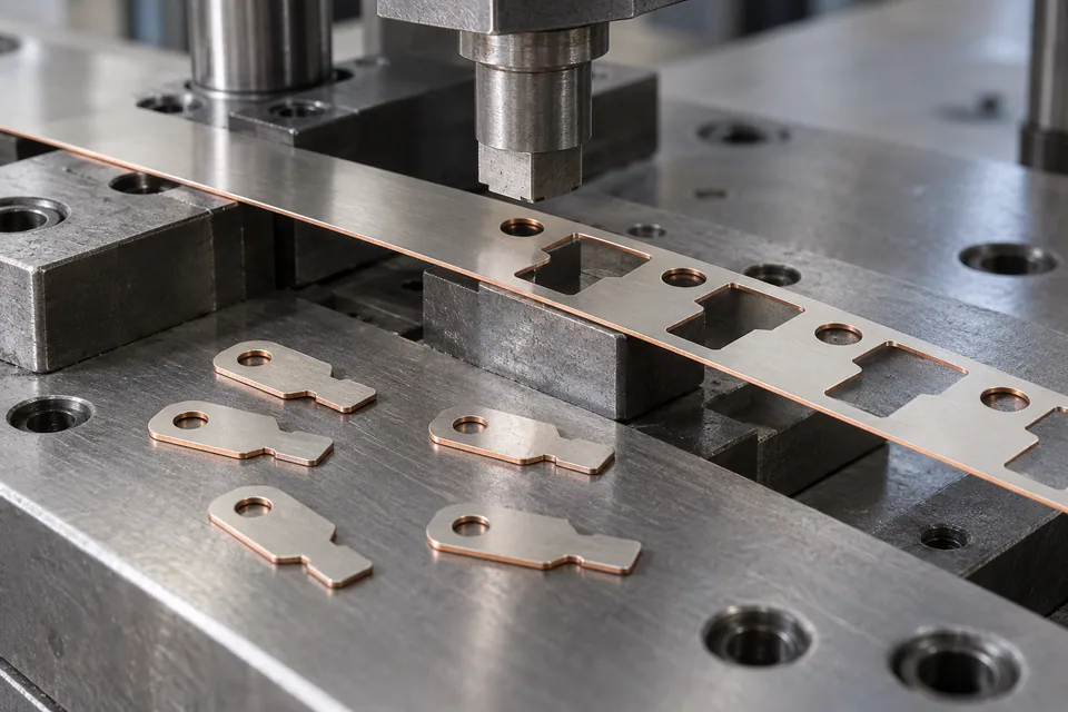
Raytron identifies nickel-clad copper in strip form for battery and electrical connections and warns against treating cladding as plating. DLX describes nickel-clad copper sheet and CAD-based stamping of interconnect tags. These sources support a shaped-part trial on a specified bonded stock, not a claim that any nickel-to-copper construction can be stamped to a common tolerance. This guide addresses a loose strip fed into a punch and die to produce a buyer-drawn flat contact blank with holes or shaped terminals. It excludes the later weld, bend and electrical approval. Both metals and their interface must remain intact around the profile, especially where a narrow bridge, hole or contact tongue concentrates load.
Updated
Where This Cutting Application Appears
Place the functional face on the part layout
Obtain the nickel-on-one-side or nickel-on-both-sides drawing and mark the intended joining face. Nest the blank so each weld land, hole and edge exposes only what the buyer accepts. Preserve strip direction and lot in the tool plan; a flipped strip may put the wrong metal at the mating interface.
Trial the most difficult geometry first
Use a short sample run with the real punch, die and stripper arrangement. Inspect a narrow tab root, internal corner and pierced hole before committing to a full progressive layout. Compare top and bottom edges for copper rollover, nickel skin separation and slugs adhering to the die.
Separate contour quality from bond quality
Measure the flat blank outline and hole-to-edge locations on a stable fixture. Section selected cut edges and bend-prone corners to see whether cladding lifts under the stamping strain. Retain first, middle and last parts with skeleton strips to detect tool-wear changes.
Pass the blank to the component maker
Protect the intended nickel contact surface during ejection and packaging. The owner should weld or join the blank to its actual mating material and inspect joint resistance and peel behavior by its own method. A clean blank proves neither long-term corrosion resistance nor battery-cell compatibility.
Define the Required Cut Result
- Blank only released part contours from specified bonded stock.
- Hold feature locations and protect contact faces.
- Detect nickel-layer lift and unacceptable exposed core at cut edges.
- Keep slugs and skeleton scrap away from usable blanks.
Problems to Diagnose Before Changing the Knife
Layer peels at a narrow tab neck
- Review incoming bond quality and die support.
- Compare strain at the neck with a broader pilot shape.
Pierced slugs stick to the part
- Inspect punch finish, stripping and scrap path.
- Check whether adhered slugs scratch the nickel face.
A correct outline has the wrong joining face
- Verify stock orientation and one-sided clad map.
- Check part ejection and stack orientation labels.
Knife Forms That May Be Considered
| Possible knife form | When it may be considered | What must be confirmed |
|---|---|---|
| Matched punch and die with controlled stripping | For a customer-approved contact contour or pierced feature on actual clad stock. | Check both-face geometry, cross-section adhesion and scrap removal. |
Information to Send for Technical Review
You do not need to know the exact blade name. Send the available workpiece, machine, current-knife and cut-result information so the application can be reviewed against a drawing or sample.
- Clad structure and interface acceptance specification
- Actual strip alloy, thickness and temper
- Required nickel contact face and strip direction
- Part contour, holes, bridges and feed carrier
- Die support, stripping and slug collection
- Exposed-copper and layer-lift criteria
- Blank packing and surface protection
- Joining and electrical test responsibility
Questions About This Cutting Application
Can plated copper die settings be copied?
No. A bonded nickel layer has an interface that needs separate edge and adhesion checks.
Why keep the skeleton strip?
It reveals torn bridges, slugs and edge damage that may be hidden on accepted parts.
Is a hole profile enough to select a die?
No. The material construction, support and allowed exposed metal also govern the trial.
Does blanking prove the contact can be welded?
No. Joining is qualified on the specified mating material after cutting.
What should accompany an RFQ?
Send a clad-strip sample, layer drawing, part outline and edge acceptance examples.
Public references and scope
These public sources provide material, cutting-method or safety context for this guide. Supplier pages describe their own materials or equipment; they do not establish a MEIRENTE blade specification or performance claim. Confirm the actual grade, machine setup and required cut with a drawing or sample.
Related product and service information
- Nickel-Clad Copper Strip Precision Coil Slitting Blades - nickel-clad copper strip · precision coil slitting
- Rolled-Annealed Copper Foil Precision Blanking Blades - rolled-annealed copper foil · precision blanking
- Ultra-Thin Stainless-Steel Foil Precision Blanking Blades - ultra-thin stainless-steel foil · precision blanking
Request a Custom Cutting-Knife Review
Send the workpiece details, machine or holder information, current knife photos or sample, required quantity and examples of the present cut problem. Final dimensions, material, edge geometry and tolerances are confirmed from the approved requirements.