
Blade Application Guides / Application Guide / Electronic metal converting
Tin-Plated Copper Strip Precision Blanking Blades
Sumitomo Metal Mining states that tin-plated copper and brass strip retains press workability and can be formed into complicated shapes. Brenscheidt specifically lists electrochemically tin-plated punched strip for electrical components. Together they establish tin-plated stock and punched electrical strip as feasible supply forms, but Brenscheidt does not establish whether plating occurs before or after punching. Neither source establishes the geometry or finish requirements of a new customer terminal. This guide covers precision blanking of a flat connector contact from an identified plated coil, including holes or carrier bridges shown on a released drawing. It does not assume that every connector is preplated: the buyer must specify whether tin is applied before or after stamping. Punch quality should be judged at the part edge, pierced features and plated functional face, then the finished connector must pass its own electrical and assembly tests.
Updated
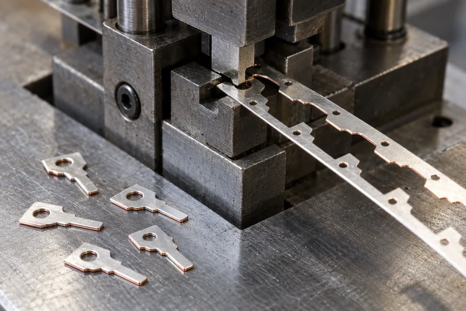
Where This Cutting Application Appears
Confirm the plating and stamping order
Read the part drawing and process traveler to learn whether the incoming strip is fully or selectively tin plated. Place functional tin areas, carrier bridges and any solder or mating faces on the strip layout. A blanked cross section may expose copper even when both broad faces are coated.
Test the most fragile feature
Punch a small trial with the specified die and stripper. Inspect a narrow terminal tine, internal hole and corner for tin flaking, copper burr and slug drag. Review whether lubricant, contact pressure or die wear marks the plated face. Keep both first and later strokes as evidence.
Inspect part and skeleton together
Measure hole position, outer contour and part flatness. Examine cut-edge cross sections and the skeletal web for torn bridges or stuck slugs. A part can meet its outline drawing yet carry a plating flake that interferes with later contact surfaces.
Release to connector qualification
Package blanks so mating faces do not abrade one another and label burr direction. The buyer should run forming, soldering or crimping on real mating hardware and test contact resistance and durability by the applicable device plan. Blanking alone does not certify any of those outcomes.
Define the Required Cut Result
- Produce the specified terminal outline and pierced features.
- Limit burrs and coating flake at functional edges.
- Keep slugs and skeleton scrap clear of good parts.
- Preserve orientation and plated-face traceability.
Problems to Diagnose Before Changing the Knife
Tin flakes from a pierced hole
- Compare incoming adhesion and die edge condition.
- Inspect both punch-entry and die-exit faces.
A small slug remains on the blank
- Review stripper, punch surface and scrap route.
- Check damage to the mating face.
Carrier bridge tears early
- Review layout, bridge width and feed support.
- Compare the skeleton at start and end of trial.
Knife Forms That May Be Considered
| Possible knife form | When it may be considered | What must be confirmed |
|---|---|---|
| Matched punch and die | For a released plated-strip contact outline and specific supply finish. | Check feature positions, exposed copper, burr and coating damage. |
Information to Send for Technical Review
You do not need to know the exact blade name. Send the available workpiece, machine, current-knife and cut-result information so the application can be reviewed against a drawing or sample.
- Copper alloy, temper and coil lot
- Tin finish, thickness and coverage map
- Plating-before-or-after-stamping sequence
- Contour, holes and carrier layout
- Functional mating or solder faces
- Permitted burr, flake and exposed substrate
- Die, stripping and scrap collection
- Finished contact test responsibility
Questions About This Cutting Application
Can a plated coil be stamped?
Yes, Sumitomo describes press-workable tin-plated strip. Confirm the specific finish, plating sequence and terminal through a trial.
Does the cut edge retain full tin coverage?
Not necessarily when the strip was plated before blanking; inspect the cross section.
Why keep skeleton scrap?
It reveals torn feed bridges and retained slugs that can damage later parts.
Can blanking certify electrical contact?
No. The assembled connector requires its own tests.
What should an RFQ contain?
Send the coil sample, plating map, terminal drawing and burr or flake limits.
Public references and scope
These public sources provide material, cutting-method or safety context for this guide. Supplier pages describe their own materials or equipment; they do not establish a MEIRENTE blade specification or performance claim. Confirm the actual grade, machine setup and required cut with a drawing or sample.
Related product and service information
- Tin-Plated Copper Strip Precision Coil Slitting Blades - tin-plated copper strip · precision coil slitting
- Rolled-Annealed Copper Foil Precision Blanking Blades - rolled-annealed copper foil · precision blanking
- Ultra-Thin Stainless-Steel Foil Precision Blanking Blades - ultra-thin stainless-steel foil · precision blanking
Request a Custom Cutting-Knife Review
Send the workpiece details, machine or holder information, current knife photos or sample, required quantity and examples of the present cut problem. Final dimensions, material, edge geometry and tolerances are confirmed from the approved requirements.