
Blade Application Guides / Application Guide / Sealing material converting
Foam Sealing Strip Cutting Without Compression Set
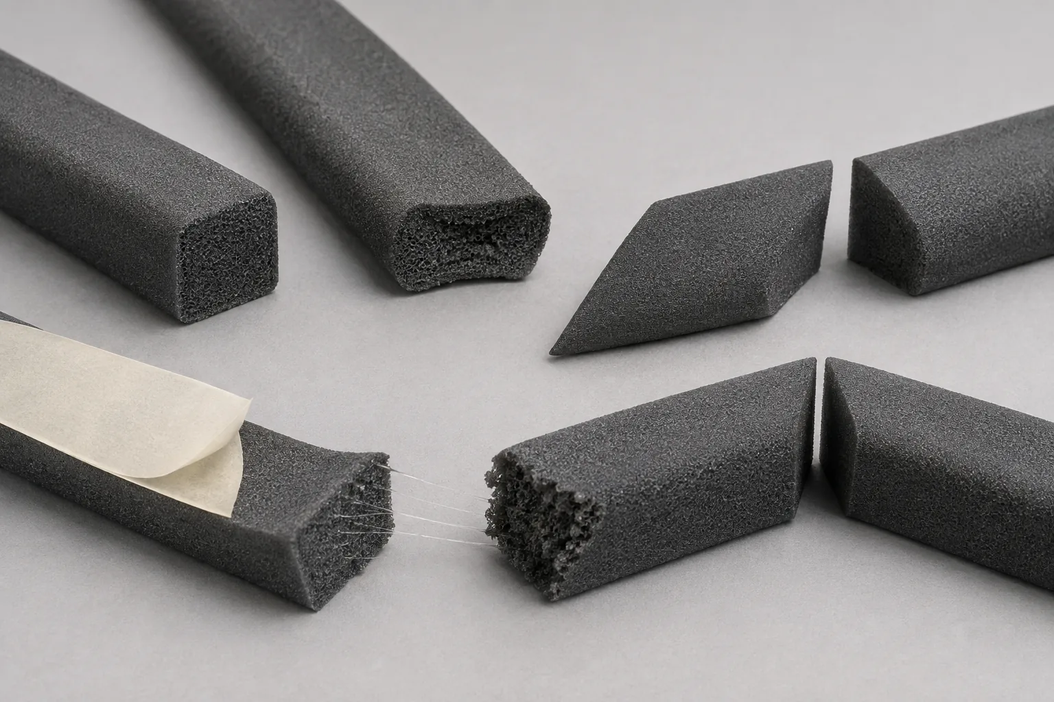
Foam sealing strip deforms easily under feed rollers and clamps, so a part can change length or end shape after it leaves the cutting station. Cell structure, density, skin, adhesive backing, release liner, profile, temperature, and recovery time must be defined before judging a straight, mitered, or notched cut.
Updated
Where This Cutting Application Appears
Straight-cut weather and enclosure seals
Extruded or converted foam strip is cut into defined lengths for doors, covers, panels, or housings after its relaxed measurement condition is established.
Mitered ends for rectangular seal frames
Profile strips receive angled end cuts that meet at corners without crushing the foam skin or shifting an adhesive-backed face.
Notched and stepped foam joint pieces
Local cutouts or stepped ends are formed for overlaps, cable passages, clips, or other drawing features while narrow foam sections remain attached.
Length And Profile Cutting process boundary
length and profile cutting for foam sealing strips is a linked sequence: the output condition and datum from each operation become the controlled input for the next. It should not be evaluated as one generic cut or accepted only by the final dimension.
Length And Profile Cutting setup checkpoint
For foam sealing strips, define the operation order, intermediate dimensions, registration transfer, material support, web or part handling and waste route for every stage of length and profile cutting.
Length And Profile Cutting acceptance checkpoint
Verify both intermediate and final results from length and profile cutting, including dimensions, registration, edge or feature quality, material damage, waste separation and stable transfer between stages.
Define the Required Cut Result
- Achieve the specified relaxed length after feed and clamping compression have dissipated
- Keep straight and mitered end faces flat enough to meet their mating joint geometry
- Separate open- or closed-cell material without tearing skins or pulling cell walls
- Cut adhesive and liner cleanly without strings, backing shift, or exposed sticky tabs
Problems to Diagnose Before Changing the Knife
The strip finishes short after recovering from the cut
Review roller compression, feed tension, stop pressure, foam density, profile shape, temperature, cut dwell, release timing, and measurement delay.
The end face is crushed, concave, or angled
Check clamp contact, blade motion, edge friction, support gap, profile orientation, foam stiffness, adhesive-side position, and blade deflection.
Cell walls tear or a surface skin peels at a corner
Compare open- or closed-cell structure, skin thickness, notch radius, cut direction, knife geometry, speed, support, aging, and local material defects.
Adhesive strings or liner tabs remain attached to the end
Examine adhesive coat, liner material, stack alignment, temperature, compression, cut depth, edge cleanliness, release force, and liner overhang.
Knife Forms That May Be Considered
| Possible knife form | When it may be considered | What must be confirmed |
|---|---|---|
| Straight guillotine cutoff knife | Consider for repeated perpendicular or angled cuts where the foam profile can be located without excessive compression. | Confirm profile section, foam structure, blade angle, stroke, support, clamp shape, feed method, recovery time, and end-face criteria. |
| Profile die or shaped cutting knife | Consider for notches, steps, paired miters, or other repeated end geometry defined by a dimensioned drawing. | Confirm minimum feature width, corner radii, foam orientation, adhesive and liner stack, ejection, mounting, nesting, and production sample. |
Information to Send for Technical Review
You do not need to know the exact blade name. Send the available workpiece, machine, current-knife and cut-result information so the application can be reviewed against a drawing or sample.
- Foam polymer, open- or closed-cell structure, density, hardness or compression data, and skin condition
- Strip cross-section with width, height, hollow or bulb features, extrusion direction, and dimensional variation
- Adhesive type and coat position, carrier layer, release-liner material, overhang, and peel direction
- Straight, mitered, notched, or stepped end drawing with angles, radii, lengths, and tolerances
- Defined conditioning temperature, relaxation time, measurement pressure, and accepted joint-fit method
- Feed rollers, compression, stop, clamp geometry, support, blade motion, cycle rate, and interface drawing
- Required cell-edge, surface-skin, adhesive-string, liner-tab, and end-squareness limits
- Representative profile coils, aged and fresh samples, failed ends, downstream frame assembly, and packing arrangement
Questions About This Cutting Application
Why is a foam strip short even when the feed measurement is correct?
Feed rollers or clamps may compress and stretch the profile during measurement. The strip then recovers after release, so relaxed length must be correlated with the feed setting.
How should foam-strip length be measured repeatably?
Define conditioning, relaxation time, surface, datum, and measurement pressure. Avoid stretching a soft profile or flattening a bulb while checking length.
What makes a mitered foam joint open at the outside corner?
Angle error, crushed end faces, unequal recovered lengths, profile twist, adhesive shift, or a cutting datum that ignores the foam cross-section can create a gap.
Can adhesive-backed foam be evaluated using an uncoated sample?
Only for limited preliminary review. Adhesive and liner alter stiffness, friction, cut completion, compression recovery, and end cleanliness, so the final stack needs confirmation.
Why do open-cell and closed-cell foams leave different edges?
Their cell walls, density, skin, elastic recovery, and tear paths differ. Confirm the actual grade and profile rather than selecting from the generic foam name.
Related product and service information
- Industrial Rubber Sheet Cutting Without Edge Deformation - industrial rubber sheets · sheet cutting
- Rubberized Tire Cord Slitting Without Cord Pullout - rubberized tire cord fabric · bias and strip slitting
- Gasket Sheet Profile Cutting for Clean Bolt Holes - compressed gasket sheet · profile cutting
Request a Custom Cutting-Knife Review
Send the workpiece details, machine or holder information, current knife photos or sample, required quantity and examples of the present cut problem. Final dimensions, material, edge geometry and tolerances are confirmed from the approved requirements.