
Blade Application Guides / Application Guide / Semiconductor wafer thinning and backgrinding
Semiconductor Wafer Backgrinding Tape Cutting Blades
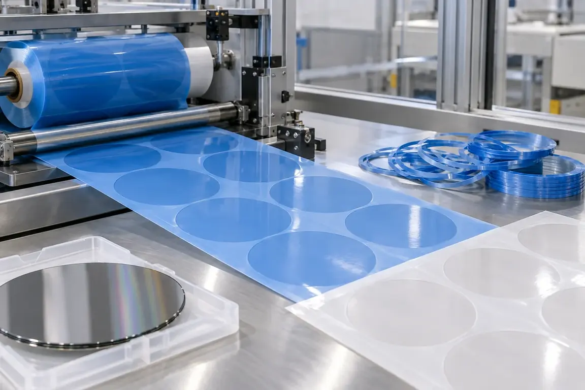
Semiconductor wafer backgrinding tape cutting blades trim temporary protection tape around the wafer contour after controlled lamination or prepare equivalent pre-cut profiles for the customer's process. The review must define the actual tape construction, adhesive side, wafer or surrogate reference, cutting path, release-liner state, scrap-ring removal and accepted edge result. It must not infer wafer dimensions, tape chemistry or machine settings from the application name.
Updated
Where This Cutting Application Appears
Post-lamination wafer contour trimming
Excess protection tape is separated along the controlled wafer reference after the tape has been applied.
Pre-cut protection-tape preparation
Liner-supported tape profiles are prepared for a process that applies an already defined protective shape.
Scrap-ring separation
The surrounding adhesive tape waste is released and removed without pulling the retained protective area.
Wafer-Contour Cutting After Tape Lamination process boundary
Wafer-contour cutting after tape lamination for Semiconductor wafer backgrinding protection tape is planned around following a specified shaped boundary or cross-section rather than making only a straight sizing cut; it is not simple rectangular sizing, longitudinal slitting or narrow edge trimming.
Wafer-Contour Cutting After Tape Lamination setup checkpoint
For Semiconductor wafer backgrinding protection tape, confirm drawing geometry, minimum radii, entry and exit points, support near direction changes, registration and shaped-waste removal.
Wafer-Contour Cutting After Tape Lamination acceptance checkpoint
For Semiconductor wafer backgrinding protection tape, evaluate complete profile dimensions, radius and tangent fidelity, corner condition, local distortion, edge quality and fit in the next assembly.
Define the Required Cut Result
- Continuous circular or controlled profile separation without attached film strands.
- Stable edge location relative to the process datum or approved surrogate sample.
- Protection tape that remains flat and adhered in the required retained area.
- Clean scrap removal without avoidable contact, particles or adhesive transfer.
Problems to Diagnose Before Changing the Knife
Tape lifts or wrinkles beside the cut path
- Confirm the actual tape, lamination sequence and condition at the time of cutting.
- Map where lifting begins relative to feed direction and circular tool movement.
- Review local support and contact without assigning unconfirmed adhesive properties.
Adhesive strings remain between tape and scrap
- Inspect the retained edge and scrap ring using the customer's normal method.
- Observe whether stringing begins during cutting or during waste removal.
- Compare material dwell and handling sequence for accepted and rejected samples.
Cut path shifts from the wafer reference
- Confirm the centering datum, vision reference or mechanical location method.
- Record whether position error is directional, intermittent or progressive.
- Compare the cut path and reference on the same completed sample.
Scrap ring does not release cleanly
- Identify connected points and the direction used to remove the surrounding waste.
- Review starts, stops and profile transitions around the complete circumference.
- Confirm whether waste removal disturbs the retained tape or introduces particles.
Knife Forms That May Be Considered
| Possible knife form | When it may be considered | What must be confirmed |
|---|---|---|
| Machine-integrated circular trimming blade arrangement | For cutting applied protection tape around a wafer or approved process surrogate. | Tape construction, contour reference, machine interface, support, cutting path and accepted retained edge. |
| Registered flat profile cutting arrangement | For preparing liner-supported protection-tape profiles before application. | Profile drawing, liner arrangement, registration method, cut result by layer and waste removal. |
| Indexed kiss-cutting arrangement | When selected tape layers must be profiled while a designated release liner remains usable. | Complete layer stack, intended penetration result, repeat layout, liner integrity and transfer method. |
Information to Send for Technical Review
You do not need to know the exact blade name. Send the available workpiece, machine, current-knife and cut-result information so the application can be reviewed against a drawing or sample.
- Backgrinding tape product identification and representative supplied samples.
- Complete tape, adhesive, backing and release-liner construction if available.
- Controlled contour drawing or clearly identified approved process sample.
- Application state at cutting, material orientation and process datum.
- Machine station, support, motion and available tooling-interface information.
- Accepted and rejected edges showing lifting, strings, wrinkles and connected waste.
- Customer cleanliness, contact, inspection and disposal requirements.
- Trial quantity, operating sequence and current cutting details if available.
Questions About This Cutting Application
Can a backgrinding tape cutting blade be selected by wafer size alone?
No. The actual tape construction, application state, cutting reference, machine interface and accepted result are required.
Can a surrogate be used instead of a production wafer for an initial trial?
Only when the customer approves the surrogate and defines which support, adhesion and contour conditions it represents.
Why must scrap-ring removal be observed?
Waste removal can lift the retained tape, create adhesive strings or transfer particles after an otherwise complete cut.
What layers should a kiss-cut trial retain?
The customer must define the required result for every layer; unknown penetration requirements should not be assumed.
What photographs are useful for review?
Show the full contour and close views of lifting, strings, wrinkles, connected points and the retained edge.
Related product and service information
- Ceramic Green Tape Cutting - ceramic green tape · tape slitting and blanking
- Semiconductor ABF Build-Up Film Slitting Blades - Semiconductor package substrate build-up dielectric film · Precision roll slitting and sheeting
- Semiconductor Dry Film Resist Slitting Blades - Semiconductor dry film photoresist laminate · Clean roll slitting and edge trimming
Request a Custom Cutting-Knife Review
Send the workpiece details, machine or holder information, current knife photos or sample, required quantity and examples of the present cut problem. Final dimensions, material, edge geometry and tolerances are confirmed from the approved requirements.