
Blade Application Guides / Application Guide / Semiconductor assembly and advanced packaging
Semiconductor Die-Attach Film Slitting Blades
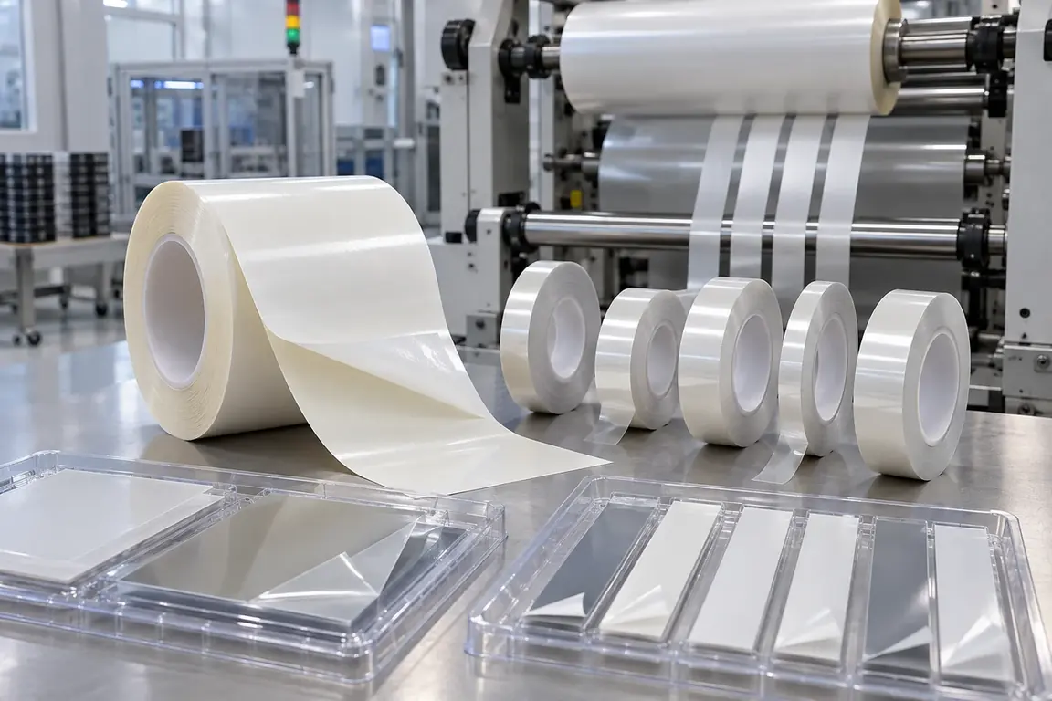
Semiconductor die-attach film slitting blades convert adhesive film laminates into widths required by assembly and advanced-packaging processes. The supplied material may include release liners, support films or integration with another process tape, so the required post-cut state must be defined layer by layer. Blade evaluation should use actual conditioned samples, the machine web path, cleanliness criteria, width plan, edge inspection and downstream transfer method rather than assumed adhesive behavior.
Updated
Where This Cutting Application Appears
Die-attach film width conversion
Master rolls are slit into controlled widths for the customer's later semiconductor assembly process.
Liner-supported edge trimming
Irregular outside edges are removed while the adhesive layer and designated release liner remain controlled.
Process-roll preparation
Separated lanes are rewound with the required adhesive-side orientation for storage, transfer or later lamination.
Liner-Supported Roll Slitting And Edge Trimming process boundary
Liner-supported roll slitting and edge trimming for Semiconductor die-attach adhesive film laminate is a linked sequence: the output condition and datum from each operation become the controlled input for the next. It should not be evaluated as one generic cut or accepted only by the final dimension.
Liner-Supported Roll Slitting And Edge Trimming setup checkpoint
For Semiconductor die-attach adhesive film laminate, define the operation order, intermediate dimensions, registration transfer, material support, web or part handling and waste route for every stage of Liner-supported roll slitting and edge trimming.
Liner-Supported Roll Slitting And Edge Trimming acceptance checkpoint
Verify both intermediate and final results from Liner-supported roll slitting and edge trimming, including dimensions, registration, edge or feature quality, material damage, waste separation and stable transfer between stages.
Define the Required Cut Result
- Continuous adhesive-film edges without strings, smearing or attached laminate fragments.
- Defined cut and retention result for the adhesive, liner and support layers.
- Controlled particles and surface contact throughout slitting and rewinding.
- Stable finished rolls without edge lift, blocking, wrinkles or avoidable lane movement.
Problems to Diagnose Before Changing the Knife
Adhesive strings or builds up at the slit edge
- Confirm the actual supplied laminate and conditioned state at the cutting station.
- Inspect where stringing begins by lane, roll side and web direction.
- Compare cleaning sequence and edge results without assuming an adhesive formulation.
Release liner is damaged or separates unexpectedly
- Define the intended post-cut state of every supplied layer.
- Inspect liner impressions, cuts and lifting across marked lane positions.
- Review bending and separation paths after the cutting point and during rewinding.
Particles or contact marks appear on usable material
- Map all rollers, supports and handling surfaces that contact the laminate.
- Determine whether debris originates at the edge or transfers from surrounding equipment.
- Use the customer's clean inspection method on accepted and rejected samples.
Finished lanes lift, wrinkle or block on the roll
- Confirm supplied roll condition and adhesive-side orientation.
- Compare lane behavior through separation, rewinding and the defined dwell period.
- Inspect finished roll faces and selected unwound sections before downstream use.
Knife Forms That May Be Considered
| Possible knife form | When it may be considered | What must be confirmed |
|---|---|---|
| Machine-matched rotary slitting arrangement | For continuous width conversion of liner-backed die-attach film on compatible roll equipment. | Layer stack, holder interface, web support, lane widths, rewind layout and accepted edge result. |
| Supported adhesive-film slitting arrangement | When the laminate requires controlled support to limit edge lift and adhesive transfer. | Conditioned material state, support location, contact restrictions, cleaning method and downstream handling. |
| Liner-supported profile kiss-cutting arrangement | When a later process requires defined adhesive-film profiles retained on a designated liner. | Profile drawing, layer order, intended cut result, registration, waste removal and transfer method. |
Information to Send for Technical Review
You do not need to know the exact blade name. Send the available workpiece, machine, current-knife and cut-result information so the application can be reviewed against a drawing or sample.
- Die-attach film product identification and representative production material.
- Complete adhesive, liner, support and process-tape layer arrangement.
- Master-roll format, finished widths, lane count and edge-trim plan.
- Adhesive-side orientation, conditioning and handling instructions provided by the customer.
- Machine station, holder interface, web path, support and rewind layout.
- Accepted and rejected edges showing strings, lift, liner damage or particles.
- Customer cleanliness, inspection, storage, transfer and packaging requirements.
- Trial quantity, production sequence and current tooling details if available.
Questions About This Cutting Application
Can die-attach film slitting blades be selected from adhesive-film thickness alone?
No. The complete laminate, conditioned state, liner result, machine interface and accepted edge must also be reviewed.
Why must every liner and support layer be identified?
The layers may require different cut outcomes and must remain correctly arranged for storage or downstream transfer.
What should be checked after rewinding?
Inspect roll faces and selected unwound sections for strings, liner lift, blocking, wrinkles and particle transfer.
How is die-attach film different from temporary wafer protection tape?
Die-attach film is intended to remain in the assembly as a bonding material, while protection tape serves a temporary process role.
Should unknown adhesive properties be estimated from appearance?
No. Keep unknown properties unconfirmed and use product documentation, actual samples and controlled trial observations.
Related product and service information
- Semiconductor Dry Film Resist Slitting Blades - Semiconductor dry film photoresist laminate · Clean roll slitting and edge trimming
- Semiconductor Wafer Backgrinding Tape Cutting Blades - Semiconductor wafer backgrinding protection tape · Wafer-contour cutting after tape lamination
- Semiconductor ABF Build-Up Film Slitting Blades - Semiconductor package substrate build-up dielectric film · Precision roll slitting and sheeting
Request a Custom Cutting-Knife Review
Send the workpiece details, machine or holder information, current knife photos or sample, required quantity and examples of the present cut problem. Final dimensions, material, edge geometry and tolerances are confirmed from the approved requirements.