
Blade Application Guides / Application Guide / RFID and intelligent label converting
RFID Smart Label Inlay Registered Die-Cutting Blades
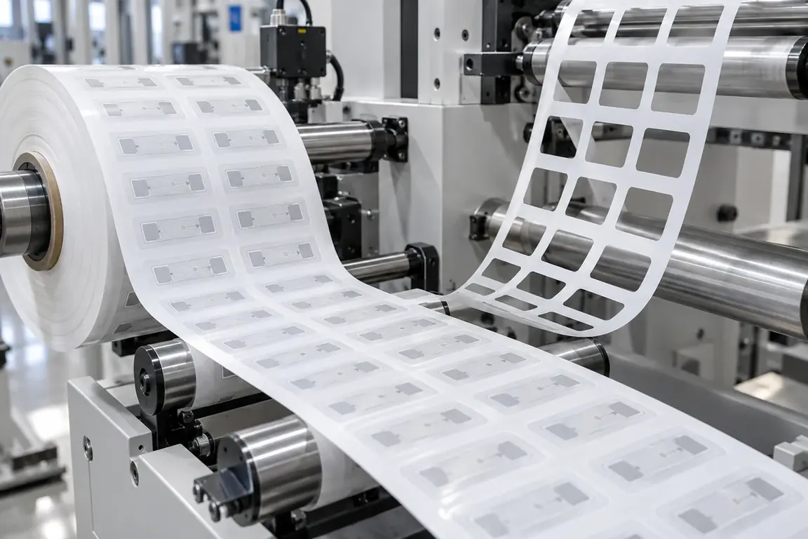
RFID smart label inlay die-cutting blades prepare repeated label profiles in a laminated web containing an antenna and integrated circuit. Review should define the inlay pitch, protected component area, registration reference, facestock and adhesive construction, required liner condition and matrix-removal path rather than treating the material as ordinary pressure-sensitive labelstock.
Updated
Where This Cutting Application Appears
Retail RFID label conversion
Printed or unprinted facestock is profiled around registered inlays while the designated release liner supports winding and application.
Logistics and asset tag production
Durable smart-label laminates are cut to an approved tag outline without entering the antenna or chip keep-out area.
Custom-shape intelligent labels
Nonrectangular profiles and application features are prepared in relation to verified inlay position and repeat layout.
Registered Rotary Die-Cutting And Kiss-Cutting process boundary
Registered rotary die-cutting and kiss-cutting for Laminated RFID smart label web with embedded inlays is a linked sequence: the output condition and datum from each operation become the controlled input for the next. It should not be evaluated as one generic cut or accepted only by the final dimension.
Registered Rotary Die-Cutting And Kiss-Cutting setup checkpoint
For Laminated RFID smart label web with embedded inlays, define the operation order, intermediate dimensions, registration transfer, material support, web or part handling and waste route for every stage of Registered rotary die-cutting and kiss-cutting.
Registered Rotary Die-Cutting And Kiss-Cutting acceptance checkpoint
Verify both intermediate and final results from Registered rotary die-cutting and kiss-cutting, including dimensions, registration, edge or feature quality, material damage, waste separation and stable transfer between stages.
Define the Required Cut Result
- Registered geometry maintained relative to the antenna, chip and web reference.
- Clean facestock and adhesive separation while the specified carrier remains usable.
- No cutting contact, pressure mark or waste movement that damages the RFID inlay.
- Stable matrix removal without lifting labels or disturbing inlay placement.
Problems to Diagnose Before Changing the Knife
Cut profile moves toward the antenna or chip
- Confirm the controlled inlay keep-out area and label-profile datum.
- Compare actual inlay pitch and lateral position across production rolls.
- Record whether error is continuous, intermittent or associated with splices.
RFID performance changes after converting
- Test inlays before and after cutting with the approved method.
- Inspect for antenna cuts, creases, pressure marks and chip-area loading.
- Review web support and waste movement near protected components.
Release liner is penetrated or weakened
- Document the full layer stack and required result for every layer.
- Inspect liner impressions at straight sections, corners and transitions.
- Compare machine support and repeatability using production material.
Matrix breaks or lifts finished labels
- Map breaks against narrow waste bridges and profile changes.
- Review peel angle, web tension and waste-removal direction.
- Check whether adhesive strings or displaced inlays obstruct separation.
Knife Forms That May Be Considered
| Possible knife form | When it may be considered | What must be confirmed |
|---|---|---|
| Registered rotary die-cutting arrangement | For continuous roll-fed profiles synchronized to inlay position. | Repeat layout, registration mark, protected zone, machine interface, liner result and matrix path. |
| Indexed flatbed profile die arrangement | For sheet-fed or indexed webs located from verified inlay positions. | Controlled drawing, datum, layer stack, support condition and part ejection. |
| Liner-retaining kiss-cutting arrangement | When facestock and adhesive separate while the designated liner remains usable. | Layer result, liner construction, peel direction, acceptable impression and approved sample. |
Information to Send for Technical Review
You do not need to know the exact blade name. Send the available workpiece, machine, current-knife and cut-result information so the application can be reviewed against a drawing or sample.
- RFID inlay type, delivery format and representative samples.
- Finished label drawing with datum and protected antenna and chip areas.
- Inlay pitch, lateral tolerance, registration mark and feed direction.
- Facestock, adhesive, carrier and release-liner layer order.
- Required result for every layer and acceptable liner condition.
- Machine station, tooling interface, web support and operating sequence.
- Matrix stripping direction, winding arrangement and accepted rolls.
- RFID inspection method plus accepted and rejected converted samples.
Questions About This Cutting Application
Why is ordinary label geometry insufficient for this review?
The profile must also be related to antenna position, chip location, inlay pitch and registration.
Should the release liner always remain uncut?
Not automatically; the required result for each layer follows the downstream application process.
How should antenna clearance be communicated?
Provide the label and inlay drawings, common datum and protected component area.
What samples help when matrix stripping fails?
Provide intact web, failed matrix, lifted labels and accepted material of the same construction.
Can a knife be selected from the RFID label name alone?
No; inlay position, layer stack, machine interface and cut result must be confirmed.
Related product and service information
- Paper Bag Patch Trimming for Consistent Bond Areas - paper bag reinforcement patches · patch trimming
- Folding Carton Die Cutting and Crease-Area Integrity - folding carton blanks · die cutting
- Solid Board Guillotine Cutting for Square Stacks - solid paperboard sheets · guillotine cutting
Request a Custom Cutting-Knife Review
Send the workpiece details, machine or holder information, current knife photos or sample, required quantity and examples of the present cut problem. Final dimensions, material, edge geometry and tolerances are confirmed from the approved requirements.