
Blade Application Guides / Application Guide / Hydrogen equipment manufacturing
Titanium Porous Transport Layer Sheet Slitting Blades
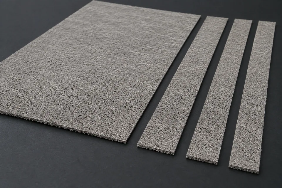
A titanium porous transport layer (PTL) is a porous metallic sheet used in some PEM electrolyzer stacks. Supplier examples include sintered titanium-fiber media; another customer PTL may have a different structure or coating. Mechanical cutting is only a candidate when the actual tolerance and edge requirements allow it. Sheet slitting makes straight strips from an approved parent sheet, so the trial must check not only width but also loose metal fibers, compressed pores, coating damage and handling cleanliness at both slit edges.
Updated
Where This Cutting Application Appears
Confirm the supplied PTL construction
Record whether the stock is a fiber, powder or other porous structure, and identify any coating, fine surface layer or designated membrane-facing side. Do not substitute a generic titanium sheet sample for the actual PTL grade.
Define the strip layout and cut method
Provide parent-sheet dimensions, target strip widths, orientation and permitted width variation. Confirm with the PTL supplier whether mechanical cutting is acceptable for the specified tolerance; other methods may need evaluation if it is not.
Protect the functional interface
Inspect each new edge for loose metal fibers, burrs and locally flattened pores. Compare both faces for coating or fine-layer damage. The buyer must define contamination and surface-contact limits for the stack interface.
Control support and collection
Use the machine drawing to review support, blade pair, arbor runout, side clearance and strip separation. Avoid rubbing the porous faces during guiding and stacking. Package samples so post-cut particles can be distinguished from handling debris.
Validate after normal handling
Measure strips at multiple positions and inspect after the normal transfer or cleaning step. The accepted PTL is a functional stack component; dimensional approval alone cannot establish electrochemical performance.
Define the Required Cut Result
- Hold straight-strip dimensions to the buyer drawing.
- Avoid loose titanium fibers, burrs and crushed pores at the cut.
- Preserve any designated fine layer or coating on both faces.
- Deliver clean strips for the buyer-defined downstream stack tests.
Problems to Diagnose Before Changing the Knife
Loose fibers project from a slit edge
- Inspect the actual porous structure and cutting direction.
- Check knife condition, overlap and local support.
- Count and classify loose fibers against the buyer acceptance method.
A strip is narrow but the edge is flattened
- Compare pore appearance at the edge with untouched stock.
- Review blade pressure, clearance and hold-down.
- Ask the PTL designer whether the affected band violates the functional interface limit.
Coating or fine layer is disturbed
- Identify which face and layer changed at cutting.
- Inspect contact points at knife, guides and collection.
- Compare a protected control sample from the same lot.
Strip width varies through the batch
- Check arbor and spacer seating, sheet registration and lateral feed movement.
- Measure several locations along each strip.
- Record any change in tension or support during the trial.
Knife Forms That May Be Considered
| Possible knife form | When it may be considered | What must be confirmed |
|---|---|---|
| Matched circular slitter knife pair | For continuous straight separation only when the PTL grade and line are validated for mechanical slitting. | Confirm arbor, spacer, edge geometry, clearance and accepted sample with the machine and PTL owner. |
| Supported straight shear set | For an intermittent straight cut on a compatible sheet line. | Confirm support, hold-down and fiber-edge quality on the actual PTL sample. |
Information to Send for Technical Review
You do not need to know the exact blade name. Send the available workpiece, machine, current-knife and cut-result information so the application can be reviewed against a drawing or sample.
- PTL supplier grade, porous structure and coating or fine-layer description
- Membrane-facing side and stock orientation
- Parent sheet and target strip drawings
- Width, edge-fiber, burr and compressed-pore limits
- Approved surface cleanliness and handling method
- Slitter or shear drawings and current setup records
- Buyer-defined downstream electrical or stack-interface tests
Questions About This Cutting Application
Can every titanium PTL be mechanically slit?
No. The supplier states that mechanical cutting is possible when tolerances allow it. Confirm the actual grade and edge criteria with a trial.
Is titanium PTL the same as solid titanium foil?
No. A PTL is porous and may include fibers, a fine surface layer or coating. Its edge and face must be inspected accordingly.
Why inspect pore damage near the cut?
Blade pressure can change a porous edge even when the strip width is correct. The buyer must define how much affected area is acceptable.
What should be checked on both faces?
Check metal-fiber debris, rub marks and any damage to a coating or fine layer, especially on a designated membrane-facing face.
Does a clean-looking edge prove stack performance?
No. The stack designer must apply its functional tests to the specified PTL and assembly.
Public references and scope
These public sources provide material, cutting-method or safety context for this guide. Supplier pages describe their own materials or equipment; they do not establish a MEIRENTE blade specification or performance claim. Confirm the actual grade, machine setup and required cut with a drawing or sample.
Related product and service information
- Electrical Insulation Paper Cutting - electrical insulation paper · sheet cutting and strip slitting
- PEM Electrolyzer Membrane Sheet Slitting Blades - PEM electrolyzer membrane · sheet slitting
- Electrolyzer Catalyst Decal Film Sheet Slitting Blades - electrolyzer catalyst decal film · sheet slitting
Request a Custom Cutting-Knife Review
Send the workpiece details, machine or holder information, current knife photos or sample, required quantity and examples of the present cut problem. Final dimensions, material, edge geometry and tolerances are confirmed from the approved requirements.