
Blade Application Guides / Application Guide / Hydrogen equipment manufacturing
Titanium Porous Transport Layer Contour Cutting Blades
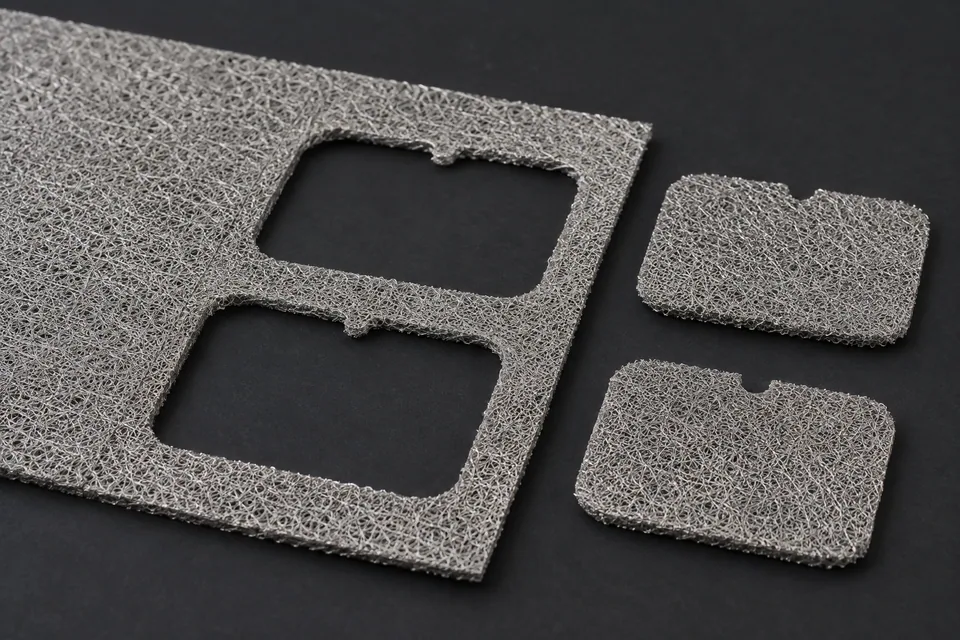
A titanium porous transport layer is a functional porous sheet in some PEM water electrolyzer designs. Contour cutting creates the required two-dimensional perimeter for stack assembly; it is not a surface-patterning or pore-making operation. Sintered, woven and other porous constructions can behave differently at an edge, and a coating may change the handling rules. Ask for the actual PTL construction, thickness, surface condition and stack drawing before discussing a profile knife. A cut trial should measure the outline and inspect pore closure, loose particles and contact-surface damage at the perimeter.
Updated
Where This Cutting Application Appears
Perimeter matched to stack geometry
Use the stack datum and gasket or flow-field interface on the buyer drawing to judge the cut outline. Separate the outer perimeter from any internal opening or registration feature; each may require a different hold-down and scrap-removal method.
Porous material support
Support the sheet close to the cut and examine both faces after release. Compression that closes pores or damages a functional coating may matter even when the outer dimensions pass. Compare with an uncut control from the same lot.
Particle and edge examination
Inspect the cut perimeter for torn ligaments, folded mesh, local densification and loose particles using the buyer’s accepted method. A sharp-looking macro edge can still shed debris during stack handling.
Assembly-oriented trial
Fit trial pieces against the actual stack drawing and inspect whether edges intrude into seal or active areas. Record orientation and coating side, if present, so a repeat cut does not reverse the intended interface.
Define the Required Cut Result
- Hold the profile and registration features to the approved drawing.
- Limit local pore collapse and loose-particle release at cut edges.
- Protect any specified surface or coating during support and ejection.
- Provide parts that fit the intended stack interface.
Problems to Diagnose Before Changing the Knife
Cut edge is compressed or smeared
- Inspect hold-down footprint and support gap.
- Compare knife sharpness and stroke or feed condition.
- Examine a cross-section against uncut material.
Particles appear after handling
- Trace debris to perimeter, internal features or upstream stock.
- Review collection and cleaning steps with the stack owner.
- Retest after the intended handling sequence.
Profile fits a gauge but not the assembly
- Recheck datum and coating-side orientation.
- Measure opening-to-edge positions and flatness.
- Compare the tool drawing with the current stack revision.
Knife Forms That May Be Considered
| Possible knife form | When it may be considered | What must be confirmed |
|---|---|---|
| Matched contour punch and die | For a repeated outline on compatible porous stock and press. | Confirm material support, clearance, part release and edge integrity on actual PTL samples. |
| Programmed nibbling punch and die | Only if the installed sheet-metal press can create the required PTL contour through overlapping strokes without unacceptable pore damage. | Trial the exact porous titanium grade; inspect scallop marks, crushed pores, loose particles and fixture support. A laser-cutting route does not use a replacement knife. |
Information to Send for Technical Review
You do not need to know the exact blade name. Send the available workpiece, machine, current-knife and cut-result information so the application can be reviewed against a drawing or sample.
- PTL construction, titanium grade and thickness range
- Coated or uncoated state and functional face orientation
- Stack drawing with datums, openings and seal interface
- Accepted edge, particle and local-compression samples
- Press or cutting machine drawing and support layout
- Part and skeleton ejection or collection plan
- Cleaning and post-cut inspection method
- Representative lot and assembly-fit trial quantity
Questions About This Cutting Application
Is contour cutting the same as making the PTL pores?
No. It creates the component outline; porosity is an existing material property that should be protected and inspected at the new edge.
Can a blade be selected from nominal thickness alone?
No. Construction, coating state, support, profile and accepted edge condition all affect the trial.
Why check the part in a stack fixture?
An outline can meet a simple dimension yet interfere with a seal or flow-field interface because of registration or orientation.
What should accompany the drawing?
Send an actual stock sample plus accepted and rejected edge and particle examples, and identify any coating side.
Public references and scope
These public sources provide material, cutting-method or safety context for this guide. Supplier pages describe their own materials or equipment; they do not establish a MEIRENTE blade specification or performance claim. Confirm the actual grade, machine setup and required cut with a drawing or sample.
Related product and service information
- Titanium Porous Transport Layer Edge Trimming Blades - titanium porous transport layer · edge trimming
- Electrolyzer Catalyst Decal Film Contour Cutting Blades - electrolyzer catalyst decal film · contour cutting
- PEM Electrolyzer Membrane Contour-cutting Blades - PEM electrolyzer membrane · contour cutting
Request a Custom Cutting-Knife Review
Send the workpiece details, machine or holder information, current knife photos or sample, required quantity and examples of the present cut problem. Final dimensions, material, edge geometry and tolerances are confirmed from the approved requirements.