
Blade Application Guides / Application Guide / Hydrogen equipment manufacturing
Electrolyzer Catalyst Decal Film Contour Cutting Blades
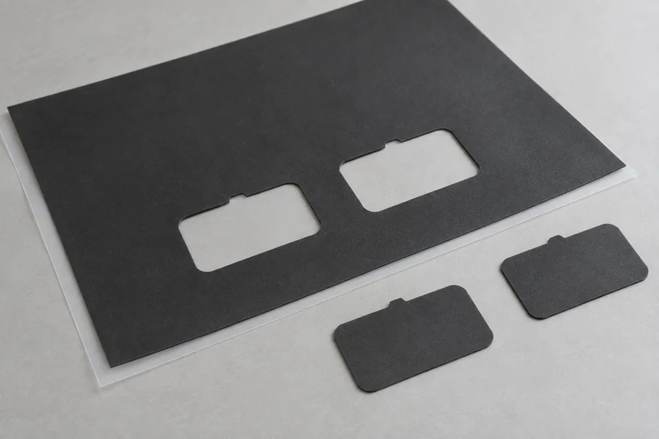
Contour cutting makes an individual shaped decal-film piece around or through a specified catalyst-coated area. Unlike sheet slitting, the finished article is a discrete profile whose registration to the catalyst patch matters for later membrane transfer. The decal substrate may be a polymer film with a coating that can crack, lift or shed particles at a cut edge. The buyer must provide a patch map and transfer datum, identify whether the catalyst may be cut, and approve an edge and face sample before tool geometry is fixed.
Updated
Where This Cutting Application Appears
Patch-to-profile location
Reference the outline to the catalyst patch or transfer fixture datum, not only to the outside of the carrier sheet. Sample several positions across a sheet to detect coating or feed registration drift.
Coated-area cutting decision
Specify whether the blade is allowed to cross a catalyst layer or must remain in an uncoated border. Examine cracking, delamination and particle shedding at the complete profile, especially corners.
Support and part release
Keep the coated face off abrasive supports. Inspect whether the profile piece curls, sticks in the die or rubs during ejection; compare with a gently separated control piece.
Handling before transfer
Mark which face and orientation are presented to the membrane. Store trial blanks so they do not contact each other’s active surfaces; recheck the outline and layer integrity after handling.
Define the Required Cut Result
- Hold the contour relative to the catalyst-patch datum.
- Avoid unacceptable cracks, flakes and face marks.
- Release each profile without distortion or missing pieces.
- Preserve orientation and traceability for the transfer trial.
Problems to Diagnose Before Changing the Knife
Profile is correct but patch is off-center
- Check how the press locates the coated patch.
- Compare feed pitch and coating placement along the sheet.
- Confirm the drawing datum matches the transfer fixture.
Coating lifts at a tight corner
- Inspect local support and punch/die alignment.
- Check whether the intended cut passes through coating.
- Compare the corner against the approved sample.
Cut piece curls after release
- Observe stripper and ejection contact.
- Inspect carrier-film tension and prior curl.
- Review stack or tray contact after the stroke.
Knife Forms That May Be Considered
| Possible knife form | When it may be considered | What must be confirmed |
|---|---|---|
| Matched contour punch and die | For repeated discrete decal profiles on a compatible press. | Confirm patch registration, carrier support and coating edge by actual-stock trial. |
| Guided profile cutting blade | For a programmed outline on a compatible flat-bed system. | Confirm backing, path, corners and release method without claiming a universal blade type. |
Information to Send for Technical Review
You do not need to know the exact blade name. Send the available workpiece, machine, current-knife and cut-result information so the application can be reviewed against a drawing or sample.
- Decal substrate, coating and layer-side details
- Patch map and finished contour drawing
- Transfer fixture datums and orientation
- Permission or prohibition for cutting coated area
- Accepted coating-edge and cosmetic samples
- Press or cutting table and support drawing
- Part/skeleton release and collection plan
- Representative sheet and transfer-trial quantity
Questions About This Cutting Application
Why is the coating patch a datum?
A correctly sized carrier blank can still place the catalyst incorrectly in the later membrane-transfer fixture.
Does contour cutting establish transfer performance?
No. It establishes profile and edge condition; transfer should be checked separately using the buyer’s process.
When should coating flakes be inspected?
Immediately after cutting and again after the intended handling sequence, including corners and internal openings.
How does this differ from trimming?
Contour cutting releases a shaped part. Edge trimming removes a narrow outside margin while keeping the main sheet.
Public references and scope
These public sources provide material, cutting-method or safety context for this guide. Supplier pages describe their own materials or equipment; they do not establish a MEIRENTE blade specification or performance claim. Confirm the actual grade, machine setup and required cut with a drawing or sample.
Related product and service information
- Electrolyzer Catalyst Decal Film Edge Trimming Blades - electrolyzer catalyst decal film · edge trimming
- Titanium Porous Transport Layer Contour Cutting Blades - titanium porous transport layer · contour cutting
- PEM Electrolyzer Membrane Contour-cutting Blades - PEM electrolyzer membrane · contour cutting
Request a Custom Cutting-Knife Review
Send the workpiece details, machine or holder information, current knife photos or sample, required quantity and examples of the present cut problem. Final dimensions, material, edge geometry and tolerances are confirmed from the approved requirements.