
Blade Application Guides / Application Guide / Spacecraft component manufacturing
Spacecraft Thermal-Control Film Shear Slitting Blades
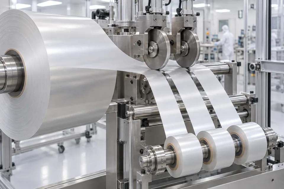
Spacecraft radiator films may use silver- or aluminum-metallized FEP, and Sheldahl also describes aluminized Kapton with selected overcoats. These are engineered film materials delivered for further fabrication; this guide does not concern a finished radiator or insulation blanket. DIENES explains that shear slitting uses overlapping upper and lower knives to separate a web. For a coated thermal-control film, the paired edge can affect the two resulting lanes differently, especially when the lower knife or support contacts a functional face. The choice of shear cutting must be qualified by the material owner on the exact substrate and deposited layers. Width and edge appearance alone cannot certify absorptance, emittance or flight durability.
Updated
Where This Cutting Application Appears
Map knife stations around the applique nest
Start with the integrator’s panel pattern and film face markings. Include only authorized trim and handling allowances. Check that the left and right child rolls retain the intended winding orientation and no two coating grades are mixed in one work order.
Measure pair engagement on representative film
Record overlap, side pressure, blade runout, web support and line tension. Check both knife faces for metal pickup or polymer smearing after a short controlled run. A fragile overcoat may call for a different tool or path; do not transfer settings from uncoated film.
Compare asymmetric slit edges
Examine both sides of each cut for curled lips, particulate deposits, cracks near the metal layer and contact tracks. Compare incoming and post-rewind samples to isolate cutting from handling damage. Track every lane to the knife pair that produced it.
Validate panel transfer separately
Measure finished reels and inspect the space-facing surface after unpacking. Have the integrator cut representative applique shapes and trial bonding or mounting. It then checks the actual optical, electrical and environmental requirements of the completed configuration.
Track each shear pair over time
Run a short first sample and another near the end of a representative reel. Note knife overlap, side load, film face, lane identity and any metal pickup on the lower knife. Compare both child edges after winding, not only immediately after the nip. If one lane degrades faster, the process owner can inspect the responsible knife pair and guide path before rejecting an entire coated-film lot. Also retain the cleaned knife and guide inspection records; they help identify whether later particles came from film deposition or the cutting station.
Define the Required Cut Result
- Maintain specified lane width with stable shear engagement.
- Protect metal and overcoat from side loading.
- Detect edge asymmetry and loose particles.
- Deliver traceable coated reels for panel fabrication.
Problems to Diagnose Before Changing the Knife
One child lane has a rolled edge
- Compare upper/lower knife alignment and side load.
- Inspect coated-face position.
- Check web tension through the nip.
Metal transfers to a knife
- Inspect local blade surface and cleaning interval.
- Compare incoming coating condition.
- Trial approved reduced-contact setup.
Pinholes appear after winding
- Locate first appearance at cut or reel.
- Review interleaf and winding pressure.
- Check trapped scrap fragments.
Knife Forms That May Be Considered
| Possible knife form | When it may be considered | What must be confirmed |
|---|---|---|
| Matched upper/lower rotary shears | Only for an owner-approved continuous coated film. | Confirm overlap, particle generation and both lane faces. |
| Stationary razor comparison | Where shear contact damages a functional overcoat. | Compare identical film lots and optical-surface criteria. |
Information to Send for Technical Review
You do not need to know the exact blade name. Send the available workpiece, machine, current-knife and cut-result information so the application can be reviewed against a drawing or sample.
- Film polymer, metal and overcoat specification
- Space-facing and bond-facing orientation
- Panel pattern and child-roll width schedule
- Upper/lower knife geometry and setting record
- Coating-contact and particle limits
- Rewind core, pressure and interleaf requirements
- Accepted two-sided edge micrographs
- Integrator optical and environmental test plan
Questions About This Cutting Application
Why can left and right edges differ?
Each lane meets a different side of the paired knives.
Is this a blanket-layer guide?
No. It concerns separate coated radiator or thermal-control film.
Does low particle count prove coating performance?
No. Optical and electrical properties require owner testing.
Can an uncoated polymer trial approve the metallized grade?
No. Use the actual construction and face orientation.
What belongs in the RFQ?
Provide coating stack, film lot, knife station drawing and accepted edge examples.
Public references and scope
These public sources provide material, cutting-method or safety context for this guide. Supplier pages describe their own materials or equipment; they do not establish a MEIRENTE blade specification or performance claim. Confirm the actual grade, machine setup and required cut with a drawing or sample.
Related product and service information
- Duct Tape Jumbo Roll Slitting Blades - duct tape jumbo roll · roll slitting
- Multilayer-Insulation Blanket Film Shear Slitting Blades - multilayer-insulation blanket film · shear slitting
- Satellite Solar-Array Cover Film Shear Slitting Blades - satellite solar-array cover film · shear slitting
Request a Custom Cutting-Knife Review
Send the workpiece details, machine or holder information, current knife photos or sample, required quantity and examples of the present cut problem. Final dimensions, material, edge geometry and tolerances are confirmed from the approved requirements.