
Blade Application Guides / Application Guide / Spacecraft component manufacturing
Multilayer-Insulation Blanket Film Shear Slitting Blades
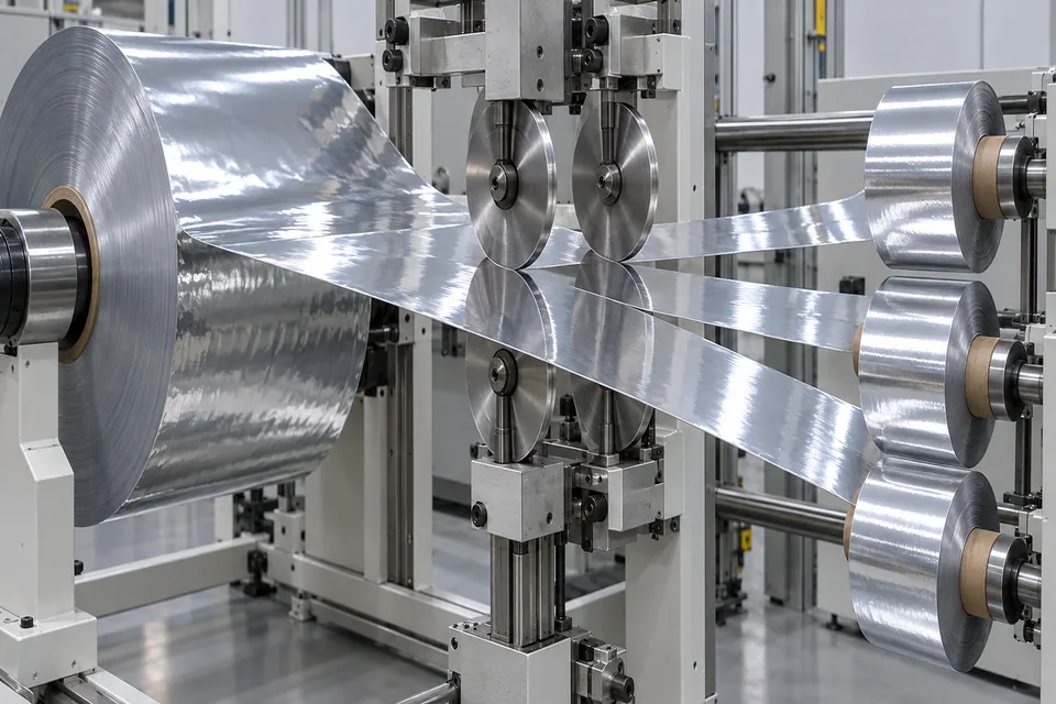
A spacecraft MLI blanket uses several distinct lightweight reflector and cover materials. Sheldahl lists metal-deposited PET, polyimide and FEP for blanket layers; NASA documents aluminized Kapton as an MLI outer-layer construction. This page addresses an individual unassembled film web, not a sewn or fastened multilayer blanket. DIENES describes shear slitting as overlapping upper and lower knives that separate a moving web into lanes. Paired-knife engagement may suit some approved film constructions but can rub a delicate coating or curl a thin edge if poorly set. Grade, deposition side and later layer location must therefore drive the trial. Dimensional inspection is only one input to the blanket maker’s thermal and mission qualification.
Updated
Where This Cutting Application Appears
Locate cuts within each film-layer plan
Take cut positions from the released MLI layer map, including outside trim and seam allowance. Some outer covers and inner reflectors use different films; do not mix them merely because they appear equally metallic. Mark the reflective side on all reels.
Record actual shear engagement
Document upper and lower knife geometry, overlap, side pressure and any support roller that touches the film. Trial at the intended web tension on a representative lot. Inspect whether either knife picks up deposited metal or produces a rolled polymer lip.
Trace fragments to the correct station
Examine left and right slit faces for flakes, burr-like metal deposits, ragged polymer and pinholes. Also inspect guides after the shear pair. Distinguish incoming coating defects from material generated at a knife or during winding.
Qualify downstream layer placement
Check lane widths and edge flatness after rewind and unpacking. Run a sample through the blanket maker’s stacking, spacer and seam sequence. Final emissivity, insulation and electrical acceptance belong to the completed configuration.
Separate knife defects from blanket-layer defects
Take an incoming control, a sample immediately after the shear pair and one after the daughter reel is unpacked. Compare edge roll, metallic particles and coating tracks at matching positions. This three-stage check matters because a thin reflector can collect debris at a guide even when the shear pair is clean. If one side of a cut is consistently worse, record which upper and lower knife surfaces touched it before changing the material route.
Define the Required Cut Result
- Keep blade engagement stable on the approved thin film.
- Hold layer width while minimizing edge roll and coating loss.
- Prevent generated flakes from reaching useful surfaces.
- Deliver identified lanes to MLI assembly.
Problems to Diagnose Before Changing the Knife
One side has a rolled metallic lip
- Compare upper and lower knife positions.
- Inspect side loading and edge wear.
- Check coated-face orientation.
Fine reflective particles appear downstream
- Inspect both knives and the first guide after cutting.
- Compare incoming and cut controls.
- Review waste and static collection.
Lane width drifts during winding
- Check web guide and knife position.
- Measure under stated tension.
- Inspect differential rewind settings.
Knife Forms That May Be Considered
| Possible knife form | When it may be considered | What must be confirmed |
|---|---|---|
| Matched rotary shear pair | When the film owner approves continuous paired-knife conversion. | Confirm low coating rub, complete separation and stable wound lanes. |
| Stationary razor comparison | Where the shear pair leaves an unacceptable lip or contact mark. | Use identical film lot and edge criteria in the comparison. |
Information to Send for Technical Review
You do not need to know the exact blade name. Send the available workpiece, machine, current-knife and cut-result information so the application can be reviewed against a drawing or sample.
- Film and metallization specification
- Inner or outer MLI layer drawing and width plan
- Upper/lower knife dimensions and overlap record
- Permitted face contact and cleaning protocol
- Accepted edge and coating microscopy
- Parent roll and finished reel specifications
- Waste extraction and clean-room instructions
- Final blanket stack, seam and thermal test plan
Questions About This Cutting Application
What is being cut?
One separate MLI film layer before blanket construction.
Why inspect both sides of a shear?
The upper and lower knives can leave different edge shapes or coating marks.
Can a shear setting transfer between PET and FEP?
No. Each polymer and coating stack needs its own trial.
Does shear slitting approve a flight blanket?
No. The assembled multilayer system must be qualified separately.
Which RFQ photo helps most?
Show both faces of a representative cut edge beside an uncut control.
Public references and scope
These public sources provide material, cutting-method or safety context for this guide. Supplier pages describe their own materials or equipment; they do not establish a MEIRENTE blade specification or performance claim. Confirm the actual grade, machine setup and required cut with a drawing or sample.
Related product and service information
- Satellite Solar-Array Cover Film Precision Cross-Cutting Blades - satellite solar-array cover film · precision cross cutting
- Spacecraft Thermal-Control Film Shear Slitting Blades - spacecraft thermal-control film · shear slitting
- Space-Grade Polyimide Adhesive Tape Shear Slitting Blades - space-grade polyimide adhesive tape · shear slitting
Request a Custom Cutting-Knife Review
Send the workpiece details, machine or holder information, current knife photos or sample, required quantity and examples of the present cut problem. Final dimensions, material, edge geometry and tolerances are confirmed from the approved requirements.