
Blade Application Guides / Application Guide / Spacecraft component manufacturing
Satellite Solar-Array Cover Film Shear Slitting Blades
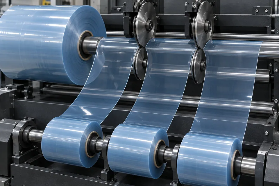
NASA technical work describes flexible solar-cell modules laminated with a transparent FEP cover sheet, while AGC identifies ETFE film as a candidate protection film for space-use perovskite cells. This guide therefore addresses only a buyer-approved, loose cover-film web for such a flexible architecture. It does not claim that cover film replaces coverglass in ordinary satellite arrays or that a candidate film has passed flight qualification. DIENES explains shear slitting with overlapping circular knives that produce narrow lanes from a wider web. A paired shear may avoid stationary-blade drag but may roll a lip or mark an optical face. The actual film stack, active cell area and later bond process must be specified before knife selection.
Updated
Where This Cutting Application Appears
Map left and right lanes to the array layout
Take cut positions from the module layer drawing, including overlap, seal and registration margins. Mark optical and bond faces and confirm whether a liner remains attached during slitting. If the buyer instead uses glass covers, this process is not applicable.
Trial upper and lower knife contact
Record overlap, side load, blade surface, web tension and which film face meets each knife. Run a representative lot through the intended speed range. Look for transparent debris and static pickup that can be difficult to see on the web.
Inspect both products of every shear pair
Compare the two new edges for rolled lips, nicks, stretch whitening and loose slivers. Inspect the central optical span separately for pressure tracks and haze. Relate every defect to its knife station and check again after winding and unpacking.
Qualify the laminated module elsewhere
Send traceable lanes to the array developer for cell registration and bonding trials. Check that the cut margin stays outside exposed cell area. The developer must verify optical throughput, adhesion, radiation durability, thermal cycling and module electrical output.
Keep film evidence tied to one architecture
Record whether the trial uses an FEP laminate design or a proposed ETFE protection film, including the specific cell and bonding stack. Compare the two edges from every shear station after they leave the reel. A transparent sliver can cling to an optical face and evade a quick inspection. Reject any extrapolation from this conversion trial to ordinary coverglass arrays. The array owner sets the environmental and electrical tests needed before a flight application.
Define the Required Cut Result
- Hold approved film lane widths and face orientation.
- Prevent knife-pair loading from damaging the optical span.
- Capture clear film particles before module assembly.
- Separate cut inspection from array qualification.
Problems to Diagnose Before Changing the Knife
One side of each slit has a folded lip
- Inspect upper/lower engagement and side pressure.
- Compare knife wear and web face direction.
- Review tension into the pair.
Faint pressure line crosses active width
- Check lower knife and nearby guide contact.
- Compare uncut transport control.
- Inspect wound reel pressure.
Slivers reappear during lamination trial
- Trace trim capture and static behavior.
- Examine both cut edges under backlight.
- Check packaging cleanliness.
Knife Forms That May Be Considered
| Possible knife form | When it may be considered | What must be confirmed |
|---|---|---|
| Paired rotary shear knives | For an approved clear cover-film web stable in a shear nip. | Confirm left/right edge shape and undamaged optical span. |
| Supported stationary razor alternative | If paired knife contact leaves unacceptable tracks. | Compare particle and optical criteria on identical film stock. |
Information to Send for Technical Review
You do not need to know the exact blade name. Send the available workpiece, machine, current-knife and cut-result information so the application can be reviewed against a drawing or sample.
- Confirmed flexible film-covered array design
- Transparent cover-film polymer, grade and stack
- Active cell area, overlap and lane drawing
- Optical and bond face orientation
- Upper/lower knife and web-path details
- Allowed edge lip, haze and particle examples
- Clean rewind and shipping method
- Buyer module-level optical, bond and space-test plan
Questions About This Cutting Application
Is this a method for cutting coverglass?
No. It applies only to loose polymer cover film in a specified flexible design.
Why inspect both shear edges?
Upper and lower knife contact can make one child edge different from the other.
Can a neat film reel establish flight suitability?
No. The finished array needs optical, environmental and electrical qualification.
Are FEP and ETFE interchangeable?
No. The buyer specifies the exact film and approved laminate design.
What trial evidence should accompany a quote?
Send both-edge images, clear-span inspection and the module layer drawing.
Public references and scope
These public sources provide material, cutting-method or safety context for this guide. Supplier pages describe their own materials or equipment; they do not establish a MEIRENTE blade specification or performance claim. Confirm the actual grade, machine setup and required cut with a drawing or sample.
Related product and service information
- Space-Grade Polyimide Adhesive Tape Kiss-Cutting Blades - space-grade polyimide adhesive tape · kiss cutting
- Multilayer-Insulation Blanket Film Shear Slitting Blades - multilayer-insulation blanket film · shear slitting
- Spacecraft Thermal-Control Film Shear Slitting Blades - spacecraft thermal-control film · shear slitting
Request a Custom Cutting-Knife Review
Send the workpiece details, machine or holder information, current knife photos or sample, required quantity and examples of the present cut problem. Final dimensions, material, edge geometry and tolerances are confirmed from the approved requirements.