
Blade Application Guides / Application Guide / Spacecraft component manufacturing
Spacecraft Thermal-Control Film Precision Cross-Cutting Blades
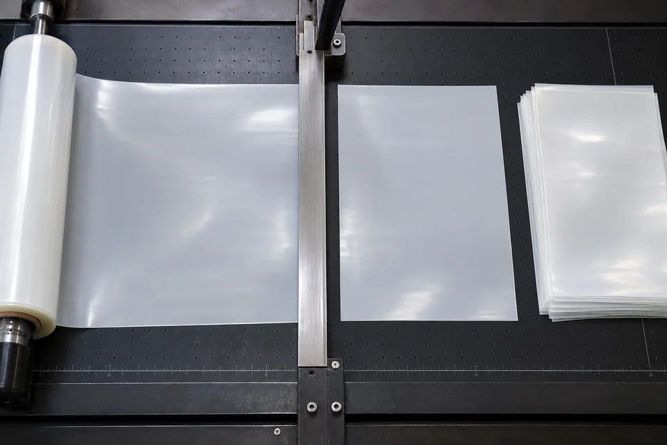
Sheldahl describes radiator films built on metallized FEP or aluminized Kapton with tailored coatings. Such material can be converted as an individual web before it becomes part of a spacecraft thermal-control surface. A cross-cut station, as Rosenthal documents for flexible film, can produce discrete flat sections. “Precision” is defined by the customer’s released blank length, squareness and coating acceptance rather than a generic blade promise. Film orientation matters because a space-facing coated side may differ from the side later bonded to a panel. This page excludes cutting attached films from spacecraft hardware and does not treat a clean blank as proof of solar absorptance, emittance, charge control or environmental durability.
Updated
Where This Cutting Application Appears
Build a thermal-surface blank schedule
Translate each applique or radiator drawing into length, width, edge allowance and face orientation. Distinguish FEP radiator material from MLI reflector film even if both look silver. Mark coil direction and coating lot in the traveler.
Choose a clean transverse support
Trial the exact film with the cutter hold-down, knife stroke and takeaway table. Check whether the coating touches rollers or is pressed into an abrasive particle. Verify complete separation at both edges without dragging a torn tail.
Inspect dimensions and optical face
Measure each blank under a consistent, low-tension method. Check squareness, wrinkles, pinholes, metal flakes and overcoat scratches under agreed lighting. Inspect the stack after interleaving; contact marks may develop after cutting rather than at the blade.
Transfer to panel fabrication
Package blanks so their coated face and lot remain clear. Trial downstream contour cutting, bonding or mechanical mounting as applicable. The spacecraft integrator validates finished thermal, charging and space-exposure behavior to its design requirements.
Use the real panel blank as the trial geometry
A clean center-of-roll coupon may miss defects at the widest applique or near the outer coil edge. Cut a representative long blank and a short blank, then inspect their four corners and the active coated field. Keep a parent-web control to distinguish incoming deposition pinholes from crosscut damage. Test the interleave and pickup method that the panel integrator will use; a correct dimension is not enough if the reflective face is scuffed during transfer. Give the integrator a marked sample showing the intended bonding side so the trial can reveal reversed-face handling before production.
Define the Required Cut Result
- Meet released radiator-film blank dimensions.
- Protect deposited and overcoated faces during feed and stacking.
- Prevent crosscut debris from riding on useful sheets.
- Provide traceable blanks for integrator testing.
Problems to Diagnose Before Changing the Knife
Last edge tears rather than shears
- Inspect end-of-stroke support.
- Review stop tension and knife sharpness.
- Compare left and right web edges.
Silver surface scratches after stacking
- Inspect interleaf and takeaway surface.
- Check incoming coating.
- Locate first appearance by sample sequence.
Blank length is inconsistent
- Check feed encoder and roll slip.
- Measure under stated tension.
- Review crosscut timing after stops.
Knife Forms That May Be Considered
| Possible knife form | When it may be considered | What must be confirmed |
|---|---|---|
| Supported transverse shear cutter | For a loose coated film web approved for discrete blanks. | Confirm full cut, square corners and low face contact. |
| Sheet-fed straight cutter | Where the owner supplies flat thermal film rather than a roll. | Check identical coating and dimensional criteria. |
Information to Send for Technical Review
You do not need to know the exact blade name. Send the available workpiece, machine, current-knife and cut-result information so the application can be reviewed against a drawing or sample.
- Exact substrate, metal and overcoat stack
- Radiator or applique blank drawing
- Parent film width, lot and winding direction
- Space-facing and bond-facing face map
- Hold-down and takeaway surface details
- Allowed pinholes, scratches and particles
- Interleaf and packaging instructions
- Integrator optical/electrical/environmental acceptance
Questions About This Cutting Application
Is this a cut on installed spacecraft film?
No. It sections loose stock before integration.
Does “precision” set a universal tolerance?
No. The owner’s drawing defines the actual limit.
Why inspect after stacking?
A clean cut piece can be marked during takeoff or interleaving.
Can blank measurements prove radiator performance?
No. The panel and coating properties require separate tests.
What is the key RFQ material?
A grade-labeled film sample and the coated-face blank drawing.
Public references and scope
These public sources provide material, cutting-method or safety context for this guide. Supplier pages describe their own materials or equipment; they do not establish a MEIRENTE blade specification or performance claim. Confirm the actual grade, machine setup and required cut with a drawing or sample.
Related product and service information
- Spacecraft Thermal-Control Film Razor Slitting Blades - spacecraft thermal-control film · razor slitting
- Multilayer-Insulation Blanket Film Precision Cross-Cutting Blades - multilayer-insulation blanket film · precision cross cutting
- Satellite Solar-Array Cover Film Precision Cross-Cutting Blades - satellite solar-array cover film · precision cross cutting
Request a Custom Cutting-Knife Review
Send the workpiece details, machine or holder information, current knife photos or sample, required quantity and examples of the present cut problem. Final dimensions, material, edge geometry and tolerances are confirmed from the approved requirements.