
Blade Application Guides / Application Guide / Spacecraft component manufacturing
Satellite Solar-Array Cover Film Precision Cross-Cutting Blades
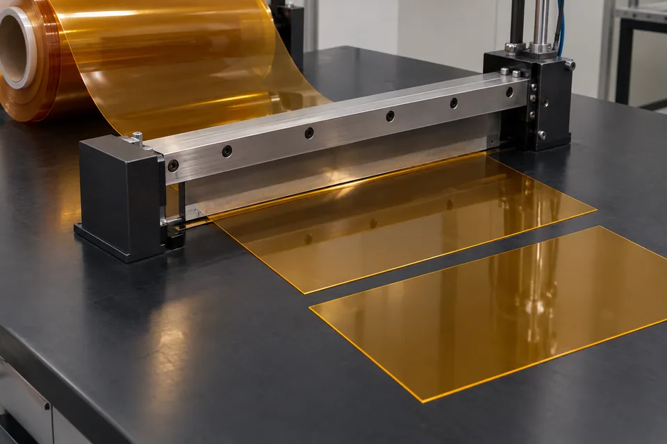
I.S.T. describes TORMED polyimide as a solar-panel coverlay and has announced transparent TORMED selected as a protective cover film for silicon solar modules in commercial satellite applications, with production preparations underway. This is a specific emerging film route, not a claim that polymer film replaces every coverglass system. Precision cross cutting here creates length-controlled flat film blanks from a qualified feed before any cell lamination; use is conditional on the buyer supplying this film format and a released array stack.
Updated
Where This Cutting Application Appears
Define the transverse blank
Use the solar-module laminate drawing to determine the cross-feed length, datums and handling margin. This straight cutoff does not shape around individual cells, busbars or interconnects; those features require a separate approved patterning process. Identify which film face will point toward incident light and whether a temporary carrier protects its optical surface.
Control surface and film movement
Support the film across its width and prevent skew during feed. Static attraction, fingerprints or fine scratches may matter more on a transparent coverlay than on an opaque backing film, so choose contact and cleaning controls with the supplier. Trial the actual coating, carrier and thickness. An apparent straight edge in a tensioned web may shift after relaxation, so use the buyer’s stated conditioning method for final measurement.
Inspect optical and mechanical edges
Measure length and squareness from the film datum, then inspect both cut ends under raking light for nicks, edge whitening, particulate and carrier delamination. Check whether the retained parent web remains flat after cutoff. For a coverlay over cells, defects extending into the active optical area need separate disposition even if overall length is correct.
Release only a material blank
Package the film to protect the light-facing surface and label grade, orientation and lot. The solar-array maker must validate lamination, optical transmission, atomic-oxygen/radiation exposure and thermal cycling for its exact design. Manufacturer mention of a coverlay does not approve any blade geometry or certify a completed space array.
Make the film trial visible
Prepare a sample that spans the full delivered width and a second sample near the smallest planned blank length. Record film face, carrier, feed direction, tool condition and inspection lighting. Recheck length and edge appearance after the blank rests under the buyer’s prescribed environment. If the supplier changes coating or carrier, repeat the trial instead of assuming identical behavior. Keep the cut records linked to optical inspection so contamination introduced at conversion can be separated from incoming-film defects.
Define the Required Cut Result
- Produce accurately oriented film blanks for array lamination.
- Protect the transparent optical surface and carrier.
- Keep cut ends free of particles and edge damage.
- Separate film conversion checks from spacecraft qualification.
Problems to Diagnose Before Changing the Knife
Clear film slips during feed
- Check hold-down, static and carrier contact.
- Measure after relaxation.
- Review registration marks outside the active area.
Edge whitening appears after cut
- Inspect tool sharpness and support.
- Compare the exact film variant in a coupon trial.
- Check handling-induced scratches separately.
Clear carrier lifts at the cut
- Check film and carrier stack before cutting.
- Inspect blade depth and takeoff angle.
- Compare first and last blanks.
Knife Forms That May Be Considered
| Possible knife form | When it may be considered | What must be confirmed |
|---|---|---|
| Guided transverse blade | For straight blank lengths on supported transparent film. | Verify clean full-width severance and surface condition. |
| Controlled sheet shear | For a released flat-stock blank route if the film is supported. | Confirm no curl, nicks or carrier shift. |
Information to Send for Technical Review
You do not need to know the exact blade name. Send the available workpiece, machine, current-knife and cut-result information so the application can be reviewed against a drawing or sample.
- Exact transparent coverlay grade and optical face
- Delivery format and temporary carrier
- Released module blank dimensions and active-area boundary
- Particulate, scratch and edge-damage limits
- Array-level environmental validation owner
Questions About This Cutting Application
Is this a cut of finished solar cells?
No. It cuts unassembled cover film before module lamination.
Does this replace conventional coverglass?
Only if the buyer’s specific array design qualifies that film construction.
Why examine particles around the edge?
The transparent active area may be sensitive to debris carried into lamination.
Is orbital qualification proven by blank dimensions?
No. The array manufacturer must validate the final stack and environment.
Does the manufacturer announcement qualify the cutter?
No. The array owner must approve the exact film, blade route and final module.
Public references and scope
These public sources provide material, cutting-method or safety context for this guide. Supplier pages describe their own materials or equipment; they do not establish a MEIRENTE blade specification or performance claim. Confirm the actual grade, machine setup and required cut with a drawing or sample.
Related product and service information
- Satellite Solar-Array Cover Film Razor Slitting Blades - satellite solar-array cover film · razor slitting
- Multilayer-Insulation Blanket Film Precision Cross-Cutting Blades - multilayer-insulation blanket film · precision cross cutting
- Spacecraft Thermal-Control Film Precision Cross-Cutting Blades - spacecraft thermal-control film · precision cross cutting
Request a Custom Cutting-Knife Review
Send the workpiece details, machine or holder information, current knife photos or sample, required quantity and examples of the present cut problem. Final dimensions, material, edge geometry and tolerances are confirmed from the approved requirements.