
Blade Application Guides / Application Guide / Spacecraft component manufacturing
Space-Grade Polyimide Adhesive Tape Kiss-Cutting Blades
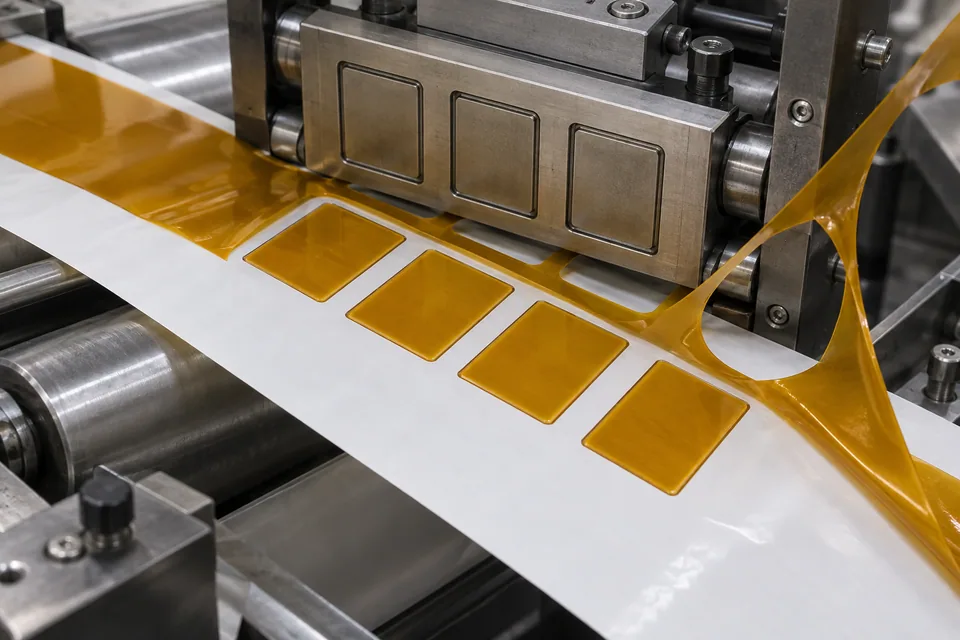
Saint-Gobain has documented custom polyimide adhesive-tape construction for a deep-space mission and states that some polyimide tapes are available with liners. Separately, 3M identifies release liners designed for kiss cutting, and tesa offers a linered polyimide-tape version for die-cut parts. Together these support a conditional kiss-cut route: only a buyer-approved tape supplied on a suitable liner may be cut through backing and adhesive while the carrier remains intact. A linerless roll requires a different process.
Updated
Where This Cutting Application Appears
Define the part and carrier
Obtain the spacecraft part drawing, spacing and the exact tape stack. Decide whether the output will be individual retained pieces or a sheet of indexed parts. Map the adhesive face and peel direction so assembly workers can lift parts without touching bond areas. A kiss cut is not complete separation of the whole stack; its defining requirement is an unbroken liner that transports the cut pieces.
Set die depth on the real liner
Trial backing, adhesive and release coating together. A cut that only marks polyimide leaves bridges; a cut driven too deep may split the carrier or release fibers into the adhesive. Check at corners and small tabs, where tool pressure may differ. Use the supplier’s approved liner rather than substituting a general-purpose sheet without a materials review.
Strip matrix and test pickup
Remove surrounding waste while watching for lifted parts, adhesive strings and film flakes. Peel sample pieces from the carrier at the assembly angle and look for liner transfer, nicked edges or distorted shapes. Repeat across the web and after storage under buyer-defined conditions. The carrier must still run through the downstream placement method without breaking.
Preserve flight acceptance
Identify lot, liner grade and die history on retained-part packs. Surface cleanliness and fit are conversion checks; bond strength, vacuum contamination and electrical or thermal function belong to the spacecraft design authority. A standard die-cut-capable polyimide tape is not automatically a flight-qualified material.
Check the parked web, not only fresh parts
After matrix removal, store a trial sheet in the format intended for delivery and then peel parts from several locations. Inspect whether backing corners have lifted, adhesive has flowed into cut gaps, or the carrier has developed splits at repeated die positions. Make a second sheet with the smallest released detail. A line that looks complete immediately after cutting can still leave hidden bridges that tear during later manual or automated pickup. Include peel-force observations from the buyer’s assembly method, since a carrier that stays intact can still release parts unpredictably.
Define the Required Cut Result
- Create retained tape parts with the liner continuous.
- Separate backing and adhesive at every contour.
- Avoid matrix-lift, adhesive transfer and carrier scoring.
- Maintain part orientation and flight-material records.
Problems to Diagnose Before Changing the Knife
Part lifts with the matrix
- Review die cut depth and release balance.
- Check narrow bridges and peel direction.
- Inspect adhesive stringing.
Liner splits during pickup
- Inspect die impression depth.
- Confirm liner grade and coating.
- Trial downstream peel angle.
Cut pieces shift on the carrier during storage
- Compare fresh and stored sheets.
- Check liner release and adhesive flow.
- Inspect delivery packaging pressure.
Knife Forms That May Be Considered
| Possible knife form | When it may be considered | What must be confirmed |
|---|---|---|
| Flatbed kiss-cut die | For repeated approved outlines on qualified lined tape. | Prove backing/adhesive separation while liner stays intact. |
| Controlled contour blade | For variable patterns on a stable carrier. | Check corner depth and matrix stripping. |
Information to Send for Technical Review
You do not need to know the exact blade name. Send the available workpiece, machine, current-knife and cut-result information so the application can be reviewed against a drawing or sample.
- Approved tape and liner specifications
- Part outline, spacing and orientation
- Carrier continuity and peel-force criteria
- Adhesive residue and particle limits
- Downstream placement and qualification tests
Questions About This Cutting Application
Can linerless tape be kiss cut this way?
No. A suitable release carrier is needed to retain the parts.
Should the die cut into the liner?
It must not compromise liner continuity; depth is proved by trials.
Why test part pickup?
Matrix removal and peeling can distort or contaminate small pieces.
Is a die-cut standard tape space qualified?
No. Mission material approval applies to the exact supplied construction.
What makes this a kiss cut?
The tape layers part while a qualified release carrier remains continuous.
Public references and scope
These public sources provide material, cutting-method or safety context for this guide. Supplier pages describe their own materials or equipment; they do not establish a MEIRENTE blade specification or performance claim. Confirm the actual grade, machine setup and required cut with a drawing or sample.
Related product and service information
- Space-Grade Polyimide Adhesive Tape Precision Cross-Cutting Blades - space-grade polyimide adhesive tape · precision cross cutting
- Multilayer-Insulation Blanket Film Razor Slitting Blades - multilayer-insulation blanket film · razor slitting
- Spacecraft Thermal-Control Film Razor Slitting Blades - spacecraft thermal-control film · razor slitting
Request a Custom Cutting-Knife Review
Send the workpiece details, machine or holder information, current knife photos or sample, required quantity and examples of the present cut problem. Final dimensions, material, edge geometry and tolerances are confirmed from the approved requirements.