
Blade Application Guides / Application Guide / Spacecraft component manufacturing
Satellite Solar-Array Cover Film Razor Slitting Blades
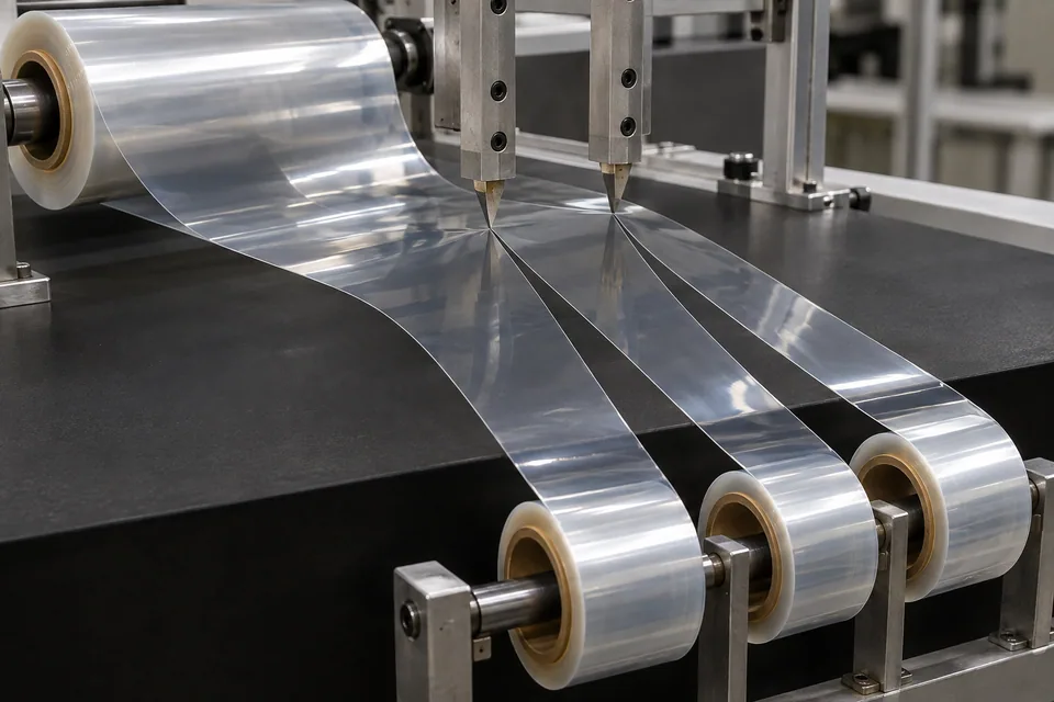
Most traditional space solar cells use individual coverglass, which is outside this guide. NASA has documented a particular flexible-array architecture in which clear FEP sheets cover and laminate solar-cell modules; AGC describes ETFE film as a potential protection material for space-use perovskite cells. Those sources establish a film-cover design category, not a universal current satellite practice. This article is conditional on a buyer supplying a transparent cover-film roll for its approved flexible array before it is joined to cells. DIENES describes a stationary razor slitting a continuous thin film web. The trial must preserve usable optical area and exclude scratches, particles and narrow edge defects. Only the array developer can establish transmission, bonding, radiation durability and electrical performance after integration.
Updated
Where This Cutting Application Appears
Confirm that the array actually uses film
Ask for a released cover-layer stack and component drawing. A conventional coverglass array has no cover-film roll to slit. Identify FEP, ETFE or another buyer-approved polymer, coating or adhesive face, and the width required by the cell string or module.
Protect the viewing and bonding faces
Trial the approved clear film through a low-contact razor path, recording which side faces guides and how the waste strip is taken away. Check whether a liner or adhesive layer travels with the web. Small blade debris or a trapped particle can become visible over a cell after lamination.
Measure the usable optical band
Inspect both slit edges for nicks, whitening, curled lips and loose slivers. Map any scratch or haze into the portion that will cover active cells. Compare with an uncut control under identical lighting; a cut edge outside the optical area may have different acceptance than a defect inside it.
Pass film lanes to the array maker
Rewind cleanly with face and lot identification. The buyer should trial registration to the cells and its approved bonding or encapsulation process. Optical transmission, adhesion, radiation durability and power output require array-level qualification.
Check whether the optical lane survives handling
Run a representative length through the chosen razor path and rewind it using the array maker’s specified orientation. Unwind a sample and inspect the light-facing field, adhesive or bonding face, and both slit edges under agreed lighting. Compare the same region with an uncut control to separate incoming haze from conversion damage. If the candidate ETFE or historical FEP architecture lacks an approved film-roll specification, stop before describing the route as production ready.
Define the Required Cut Result
- Create cover-film lanes for a specified flexible-array architecture.
- Retain transparent active width and approved edge allowance.
- Avoid particles and face scratches before lamination.
- Preserve polymer, coating and lot traceability.
Problems to Diagnose Before Changing the Knife
Haze appears beside the slit
- Compare blade drag and film tension.
- Inspect pre-cut parent film.
- Check guide contact on the optical face.
Narrow film edges curl into winding
- Review support and razor angle.
- Compare winding tension and face direction.
- Measure after approved recovery.
Clear slivers land on useful film
- Inspect blade condition and trim collection.
- Check static control approved by owner.
- Compare first and last reel layers.
Knife Forms That May Be Considered
| Possible knife form | When it may be considered | What must be confirmed |
|---|---|---|
| Supported stationary razor | Only when the buyer’s clear cover-film construction passes trial. | Confirm width, optical-face appearance and particle control. |
| Rotary shear comparison | If the razor tears or stretches the approved film. | Compare equal film lots against the same optical-area criteria. |
Information to Send for Technical Review
You do not need to know the exact blade name. Send the available workpiece, machine, current-knife and cut-result information so the application can be reviewed against a drawing or sample.
- Buyer confirmation of a film-covered flexible array
- Exact transparent film and coating/adhesive stack
- Cell-module cover width and active optical area
- Parent roll, liner, face and lot details
- Permitted guide contact and clean handling
- Edge, scratch, haze and particle limits
- Rewind and interleaf specifications
- Array bonding, optical and environmental test plan
Questions About This Cutting Application
Do all satellites use slit cover film?
No. Many designs use coverglass; this guide applies only to a specified flexible film-cover architecture.
Is NASA’s FEP example a current product approval?
No. It demonstrates a possible architecture; the buyer must approve its own material and design.
Can a transparent-looking slit prove optical transmission?
No. The array maker tests film and completed module optically.
Does the blade touch the solar cells?
No. It converts loose film before cell integration.
What starts the RFQ?
Supply the approved array layer drawing and a representative film roll.
Public references and scope
These public sources provide material, cutting-method or safety context for this guide. Supplier pages describe their own materials or equipment; they do not establish a MEIRENTE blade specification or performance claim. Confirm the actual grade, machine setup and required cut with a drawing or sample.
Related product and service information
- Satellite Solar-Array Cover Film Shear Slitting Blades - satellite solar-array cover film · shear slitting
- Multilayer-Insulation Blanket Film Razor Slitting Blades - multilayer-insulation blanket film · razor slitting
- Spacecraft Thermal-Control Film Razor Slitting Blades - spacecraft thermal-control film · razor slitting
Request a Custom Cutting-Knife Review
Send the workpiece details, machine or holder information, current knife photos or sample, required quantity and examples of the present cut problem. Final dimensions, material, edge geometry and tolerances are confirmed from the approved requirements.