
Blade Application Guides / Application Guide / Aerospace composite manufacturing
Lightning-Strike Protection Mesh Contour-Cutting Blades
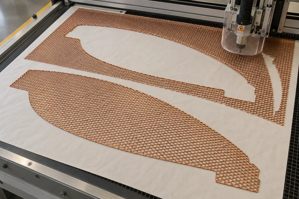
The Gill Corporation identifies STRIKEGRID as continuous expanded aluminum foil for lightning-strike protection on composite structures and says it is adaptable to ply-cutting equipment when combined with surface films. That supports contour cutting a flat, uninstalled mesh ply before layup. It does not establish a universal cut recipe for every expanded copper or aluminum grade. The cutter receives a specified foil or foil-and-film construction; a cured aircraft panel is outside this operation.
Updated
Where This Cutting Application Appears
Trace the ply outline
Begin with the released laminate ply drawing, not a photograph of the finished airframe. Mark curved perimeter segments, reliefs and any datum that fixes mesh orientation. Include drawing-defined overlap or joining regions because a visually neat edge can still remove intended conductive coverage. A nested contour should leave usable strand support at tight turns; trial pieces should include the smallest radius and narrowest neck in the real pattern.
Keep the foil supported
Expanded foil can move or snag when a strand catches the tool. Trial the delivered surface film or carrier, hold-down surface and lift sequence together. Cut a coupon both with and against the expansion direction, then inspect whether the pattern stretches or whether loose strand ends curl upward. Record the state in which dimensions are taken, including whether a temporary carrier remains attached.
Inspect around details
Review the entire shaped perimeter under magnification, particularly notches and registration openings. Look for severed strand tails, folded mesh, carrier delamination and metallic fragments. Distinguish a true internal opening on the drawing from a field added by a later composite-trim operation. A contour ply should be transferable into layup without hand-tugging on isolated strands.
Release the ply to laminate control
Compare outline, orientation and overlap regions to the composite shop drawing. Retain a sample of the cut foil for downstream layup and bonding trials. Continuity and lightning-strike performance depend on the complete laminate architecture and airframe qualification; a blade trial establishes only the cut-ply condition.
Define a repeatable coupon decision
A useful trial matrix compares the same mesh grade with each proposed support and tool path. For every sample, record the nest orientation, whether film stayed attached, the number and location of strand defects, and the amount of hand finishing needed. Reject a route that depends on manually bending strands back into place. The released process should identify inspection lighting and magnification so a future change of tool or carrier can be compared against the original qualified edge.
Define the Required Cut Result
- Form a drawing-defined curved mesh ply before laminate cure.
- Maintain expanded-foil pattern and surface-film support.
- Protect specified overlap and connection regions.
- Document loose metal and edge deformation for layup review.
Problems to Diagnose Before Changing the Knife
Strands hook or lift at corners
- Check local radius against mesh opening and strand direction.
- Compare supported and unsupported cut trials.
- Inspect blade edge for metal pickup.
Cut ply changes outline after removal
- Measure with the same carrier and conditioning state.
- Review hold-down and lift direction.
- Compare expansion direction to the nest orientation.
Knife Forms That May Be Considered
| Possible knife form | When it may be considered | What must be confirmed |
|---|---|---|
| Supported flatbed contour cutter | For flat plies whose carrier and foil respond cleanly in trials. | Confirm complete separation without stretched cells or hanging metal. |
| Profile die | For repeated released outlines after the mesh stack is qualified. | Inspect small features, ejection and tool wear on real foil. |
Information to Send for Technical Review
You do not need to know the exact blade name. Send the available workpiece, machine, current-knife and cut-result information so the application can be reviewed against a drawing or sample.
- Expanded metal alloy, coating and supplier grade
- Whether surfacing film or removable carrier is delivered
- Ply drawing, orientation and connection/overlap regions
- Permitted loose-metal and strand-tail criteria
- Layup handling and downstream qualification owner
Questions About This Cutting Application
Is this the cut on a cured aircraft panel?
No. It is a flat expanded-foil ply before composite layup.
Does every expanded mesh tolerate the same blade?
No. Alloy, strand geometry, coating and carrier change cutting response.
Why preserve overlap zones?
The released laminate drawing may require conductive coverage across ply joints.
Is a smooth edge proof of lightning protection?
No. Laminate continuity and strike performance require downstream qualification.
Public references and scope
These public sources provide material, cutting-method or safety context for this guide. Supplier pages describe their own materials or equipment; they do not establish a MEIRENTE blade specification or performance claim. Confirm the actual grade, machine setup and required cut with a drawing or sample.
Related product and service information
- Lightning-Strike Protection Mesh Cut-to-Size Blades - lightning-strike protection mesh · cut to size
- Thermoplastic PEEK Composite Tape Contour Cutting Blades - thermoplastic PEEK composite tape · contour cutting
- Cyanate-Ester Prepreg Contour Cutting Blades - cyanate-ester prepreg · contour cutting
Request a Custom Cutting-Knife Review
Send the workpiece details, machine or holder information, current knife photos or sample, required quantity and examples of the present cut problem. Final dimensions, material, edge geometry and tolerances are confirmed from the approved requirements.