
Blade Application Guides / Application Guide / Specialty metal converting
Laminated Nanocrystalline Magnetic Sheet Precision Die-Cutting Blades
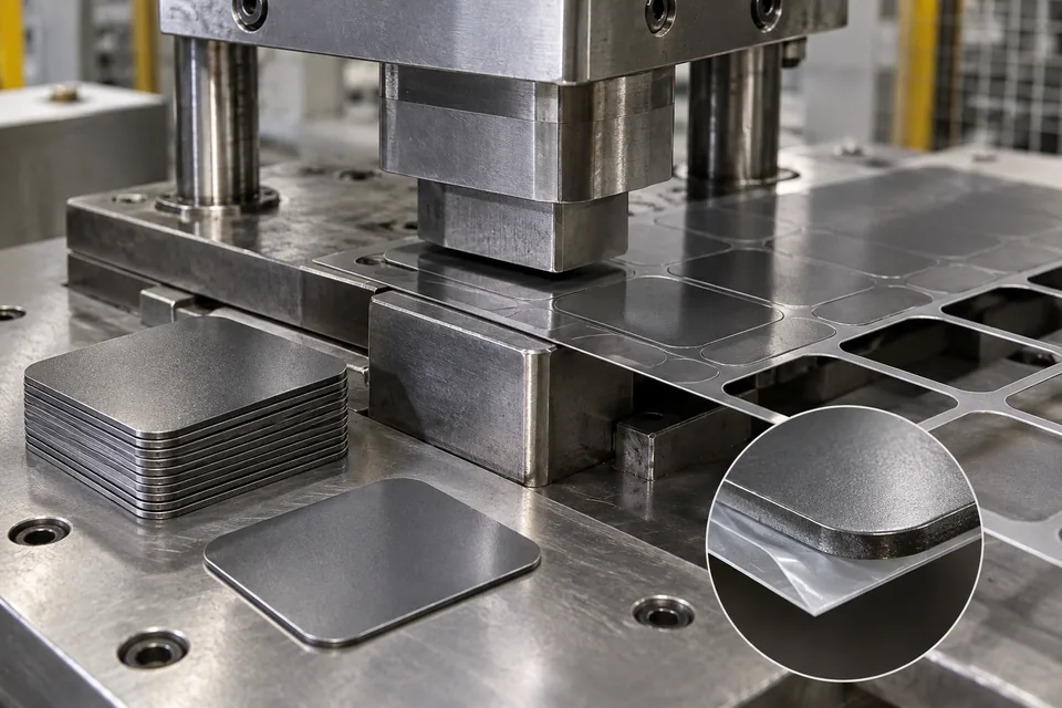
AONA describes a specific production route in which nanocrystalline strips are annealed, laminated with adhesive film and cut into individual magnetic sheets from a master coil by precision die cutting. Proterial describes laminated FINEMET magnetic sheets and says its MS-F sheet can be cut or punched; those are supported composite products, not exposed brittle bare ribbon. This guide covers a buyer-approved multilayer magnetic sheet or laminate with a released contour drawing, before integration into a shield or wireless-charging panel. Stack construction and support films differ by supplier, so a die that works on one branded sheet is not automatically suitable for another. The cut can be inspected for outline and layer damage, while shielding, permeability and wireless power behavior require tests of the actual built component.
Updated
Where This Cutting Application Appears
Identify every laminate layer and face
Obtain the exact supplier stack: nanocrystalline layer count, adhesive or polymer support, release liner and protective faces. Note whether the buyer wants a finished magnetic tile or a die-cut intermediate for a larger radial panel. Define direction markings if magnetic anisotropy has been engineered along the ribbon length.
Support the contour during die entry
Trial punch and die engagement on a short section of the actual laminated master coil. Inspect small corners, holes and narrow bridges for foil cracking, film tearing or layer slip. Keep the liner or carrier configuration specified by the owner; removing support early can change the cutting behavior.
Inspect both geometry and stack integrity
Measure contour position on a stable fixture, then inspect edge delamination, adhesive squeeze-out, detached metallic flakes and exposed layer steps. Compare top and bottom faces, including at die entry and ejection. Keep skeletal scrap from snagging a useful part or depositing fragments on the adhesive face.
Qualify the magnetic function in context
Package cut pieces without bending or peeling the laminate. The device integrator must test its panel arrangement, spacing, bonding and operating field conditions. A neat die-cut shape does not by itself establish EMI shielding or wireless charging Q factor.
Define the Required Cut Result
- Produce the released supported-laminate contour.
- Keep brittle magnetic layers attached to their carrier and adhesive.
- Control particles and exposed edge steps.
- Preserve directional identity for panel assembly.
Problems to Diagnose Before Changing the Knife
Corners shed magnetic flakes
- Inspect die sharpness, laminate support and ejection force.
- Compare incoming stack condition.
Adhesive squeezes beyond the cut edge
- Review layer stack, pressure and die clearance.
- Inspect both faces after liner removal.
Parts warp after release
- Check residual coil set, support-film stress and handling.
- Measure after the buyer’s conditioning period.
Knife Forms That May Be Considered
| Possible knife form | When it may be considered | What must be confirmed |
|---|---|---|
| Matched precision punch and die | For a specified laminated nanocrystalline sheet with an approved contour and carrier state. | Confirm feature accuracy, layer adhesion and both-face edge quality. |
| Alternative supplier-approved profile cut | If the stack cracks, delaminates or sheds flakes in a die trial. | Compare full laminate integrity and device testing. |
Information to Send for Technical Review
You do not need to know the exact blade name. Send the available workpiece, machine, current-knife and cut-result information so the application can be reviewed against a drawing or sample.
- Named laminated sheet grade and full layer stack
- Proof of support film or adhesive construction
- Contour, hole and orientation drawing
- Carrier or release-liner handling instructions
- Allowed cracks, flakes and exposed-layer criteria
- Die support, clearance and ejection method
- Stack-safe packing and cleanliness plan
- Final shield or wireless-panel test owner
Questions About This Cutting Application
Is a bare annealed nanocrystalline ribbon being punched?
No. This guide concerns a supported laminated magnetic-sheet product.
Does every laminated sheet have the same adhesive stack?
No. Use the named supplier’s construction and handling instructions.
Why track ribbon direction?
The finished panel may align that direction with magnetic field lines.
Can an accurate outline prove shielding performance?
No. Measure the integrated device under its actual operating conditions.
What should a die-cut RFQ include?
Send a laminate sample, layer stack, contour drawing and layer-defect acceptance examples.
Public references and scope
These public sources provide material, cutting-method or safety context for this guide. Supplier pages describe their own materials or equipment; they do not establish a MEIRENTE blade specification or performance claim. Confirm the actual grade, machine setup and required cut with a drawing or sample.
Related product and service information
- Nanocrystalline-Alloy Precursor Ribbon Cut-to-Length Blades - nanocrystalline-alloy amorphous precursor ribbon · cut to length
- Amorphous Metal Ribbon Precision Coil Slitting Blades - amorphous metal ribbon · precision coil slitting
- Beryllium-Copper Foil Precision Coil Slitting Blades - beryllium-copper foil · precision coil slitting
Request a Custom Cutting-Knife Review
Send the workpiece details, machine or holder information, current knife photos or sample, required quantity and examples of the present cut problem. Final dimensions, material, edge geometry and tolerances are confirmed from the approved requirements.