
Blade Application Guides / Application Guide / Electronics adhesive converting
Electrically Conductive Transfer Tape Die-Cutting Blades
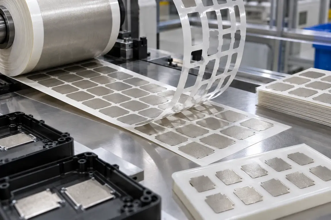
Electrically conductive transfer tape die-cutting blades create grounding, shielding or bonding shapes from pressure-sensitive adhesive containing conductive fibers, particles or a thin carrier. Review should define electrical contact areas, liner arrangement, adhesive exposure, geometry, waste-removal sequence and cleanliness because a visually complete cut can still compromise functional material.
Updated
Where This Cutting Application Appears
Electronics grounding patches
Conductive shapes are prepared for defined contact areas between housings, shields or circuit assemblies.
EMI bonding components
Profiles and openings are cut while retaining the conductive network required by design.
Liner-supported assembly parts
Converted pieces remain on a carrier for inspection, indexing and transfer.
Rotary Die-Cutting And Liner-Retaining Kiss-Cutting process boundary
Rotary die-cutting and liner-retaining kiss-cutting for Electrically conductive adhesive transfer tape with release liner is a linked sequence: the output condition and datum from each operation become the controlled input for the next. It should not be evaluated as one generic cut or accepted only by the final dimension.
Rotary Die-Cutting And Liner-Retaining Kiss-Cutting setup checkpoint
For Electrically conductive adhesive transfer tape with release liner, define the operation order, intermediate dimensions, registration transfer, material support, web or part handling and waste route for every stage of Rotary die-cutting and liner-retaining kiss-cutting.
Rotary Die-Cutting And Liner-Retaining Kiss-Cutting acceptance checkpoint
Verify both intermediate and final results from Rotary die-cutting and liner-retaining kiss-cutting, including dimensions, registration, edge or feature quality, material damage, waste separation and stable transfer between stages.
Define the Required Cut Result
- Accurate profiles matched to the controlled assembly drawing.
- Defined separation of selected layers while the specified liner remains serviceable.
- Clean conductive edges without filler pullout, loose particles or adhesive strings.
- Stable waste removal without stretching or contaminating contact surfaces.
Problems to Diagnose Before Changing the Knife
Aggressive adhesive strings between part and waste
- Identify exposed adhesive faces and liner release levels.
- Observe whether strings begin at corners or narrow bridges.
- Record material temperature and time from cutting to stripping.
Conductive scrim or filler pulls from the edge
- Identify fibers, particles, foil or other conductive carrier.
- Inspect both sides for loose conductive material.
- Review support at tight radii and narrow sections.
Release liner is penetrated or tears
- Document required results through every layer.
- Inspect impressions across the complete profile.
- Compare liner behavior during stripping, pickup and application.
Finished part shifts or stretches on the carrier
- Review web tension, adhesive anchoring and spacing.
- Check whether waste removal loads unsupported features.
- Measure parts before and after stripping.
Knife Forms That May Be Considered
| Possible knife form | When it may be considered | What must be confirmed |
|---|---|---|
| Rotary kiss-cutting arrangement | For repeated roll-fed parts retained on a release liner. | Layer stack, layout, liner result, machine interface, matrix path and contact geometry. |
| Flatbed profile die-cutting arrangement | For indexed material with outer profiles and internal openings. | Controlled drawing, support, layer result, adhesive handling, ejection and sample. |
| Compound cut-and-strip arrangement | When features and waste zones require a defined sequence. | Feature relationship, waste bridges, stripping direction, carrier and transfer method. |
Information to Send for Technical Review
You do not need to know the exact blade name. Send the available workpiece, machine, current-knife and cut-result information so the application can be reviewed against a drawing or sample.
- Conductive tape grade or construction description and samples.
- Conductive filler, scrim, foil or carrier information.
- Liner types, layer order and exposed adhesive locations.
- Part drawing with contact and protected areas.
- Required result for every layer and acceptable liner impression.
- Machine station, interface, support and feed direction.
- Matrix removal, pickup and placement sequence.
- Particle, electrical inspection and packaging requirements.
Questions About This Cutting Application
Why is this not reviewed like ordinary double-sided tape?
Conductive material, electrical contact geometry and contamination limits add functional requirements.
Does a clean-looking edge confirm electrical performance?
No; the converted part needs the approved electrical and visual inspection.
What defines a liner-retaining cut?
Every layer, intended cut result, liner condition and peel direction must be stated.
How should adhesive stringing be documented?
Show the starting location, waste direction and material condition when it occurs.
Can tooling be chosen from tape thickness alone?
No; construction, adhesive, reinforcement, profile and machine interface must be confirmed.
Related product and service information
- Foam Tape Profile Cutting Without Cell Deformation - foam adhesive tape · profile cutting
- Folding Carton Die Cutting and Crease-Area Integrity - folding carton blanks · die cutting
- Solid Board Guillotine Cutting for Square Stacks - solid paperboard sheets · guillotine cutting
Request a Custom Cutting-Knife Review
Send the workpiece details, machine or holder information, current knife photos or sample, required quantity and examples of the present cut problem. Final dimensions, material, edge geometry and tolerances are confirmed from the approved requirements.