
Blade Application Guides / Application Guide / Electric vehicle battery manufacturing
Cell-to-cell Aerogel Pad Contour-cutting Blades
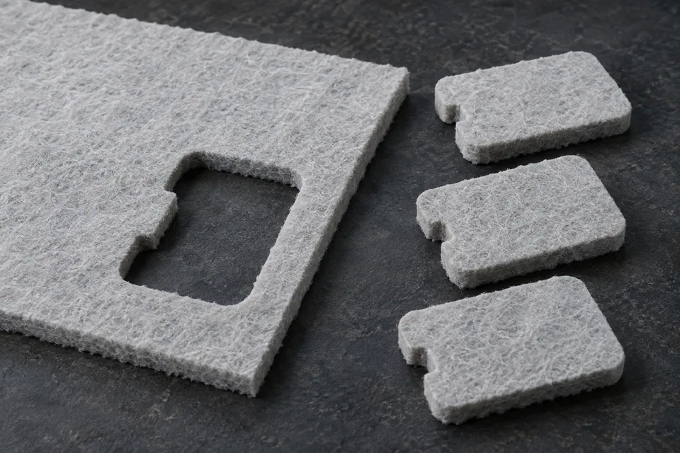
Contour cutting produces the two-dimensional outline of a cell-to-cell aerogel pad from a larger barrier sheet. The result is a discrete part sized for the cell stack, unlike longitudinal sheet slitting, which only creates lanes. Aspen states that cell barriers are tailored to mechanical compression and thermal barrier requirements and fabricates finished parts from aerogel materials. The buyer’s drawing therefore controls the profile, orientation and permitted edge condition. Any film facing, adhesive or multi-layer encapsulation must be identified before choosing a profile tool and ejection method.
Updated
Where This Cutting Application Appears
Follow the assembly datum
Tie the outer contour, corner radii and any relief cuts to the cell or module drawing. Mark top and bottom faces, especially if the barrier has asymmetric layers. Measure the trial pad as an unconstrained part and again in the intended fixture if the buyer specifies compression.
Manage internal features
If the part has a notch or opening, plan how the slug leaves without dragging through the pad surface. Avoid adding internal cuts merely for tool convenience because every opening changes the protected area and creates another potentially shedding edge.
Support the full outline
A broad support surface helps avoid local crush at the perimeter. Check whether a press stroke, programmed knife path or staged cuts will bend or peel the skin. Choose the sequence from the actual profile and material trial rather than a generic foam-cutting example.
Inspect the part after release
Review corners, notches and any tight curves for torn facing, powder, delamination and loss of thickness. Compare the fitted pad with the cell stack envelope and retain a marked control sample from the same sheet.
Define the Required Cut Result
- Match the approved pad outline and orientation.
- Retain bonded facings and a sound aerogel edge around corners and notches.
- Avoid local compression or debris on faces that meet the cells.
- Release the part and scrap without changing the finished profile.
Problems to Diagnose Before Changing the Knife
Corners tear or lift
- Inspect corner radius against the tool path.
- Compare face orientation and layer adhesion.
- Review ejection and scrap pull at that corner.
Part is dimensionally correct but too compressed
- Compare thickness at edge and central area.
- Inspect hold-down footprint and tool dwell.
- Measure after the specified recovery interval if the buyer defines one.
Small slugs stay attached
- Review cut continuity around the opening.
- Check support and slug clearance.
- Inspect the part after manual removal for new edge damage.
Knife Forms That May Be Considered
| Possible knife form | When it may be considered | What must be confirmed |
|---|---|---|
| Profile die with matched support | For a repeated pad outline when the stock and press allow full-profile cutting. | Confirm cut-through, compression and ejection on the actual material stack. |
| Programmed contour knife | For changing profiles or staged access to notches on a compatible cutting table. | Confirm path accuracy, hold-down footprint and edge quality at the smallest feature. |
Information to Send for Technical Review
You do not need to know the exact blade name. Send the available workpiece, machine, current-knife and cut-result information so the application can be reviewed against a drawing or sample.
- Pad drawing with datum, radii, notches and orientation
- Actual aerogel/facing/adhesive layer stack
- Sheet size and thickness range
- Finished-part compression and edge-shedding criteria
- Accepted pad samples and assembly-fit fixture
- Machine support, hold-down and ejection details
- Scrap and particle-control method
Questions About This Cutting Application
How does contour cutting differ from sheet slitting?
Contour cutting releases a discrete two-dimensional pad; slitting divides continuous stock lengthwise into lanes.
Can the profile be approved from a CAD outline alone?
No. Check real parts for layer lift, compression, debris and assembly fit.
Should a small notch be ignored if the main outline passes?
No. Notches can tear or retain scrap and may determine correct placement in the cell stack.
What must be shown on the sample drawing?
Identify the functional face, profile datum, all openings and the surfaces that must remain unmarked.
Public references and scope
These public sources provide material, cutting-method or safety context for this guide. Supplier pages describe their own materials or equipment; they do not establish a MEIRENTE blade specification or performance claim. Confirm the actual grade, machine setup and required cut with a drawing or sample.
Related product and service information
- Cell-to-cell Aerogel Pad Edge-trimming Blades - cell-to-cell aerogel pad · edge trimming
- Mica Battery Barrier Sheet Contour-Cutting Blades - mica battery barrier sheet · contour cutting
- Ceramic Battery Insulation Pad Contour-Cutting Blades - ceramic battery insulation pad · contour cutting
Request a Custom Cutting-Knife Review
Send the workpiece details, machine or holder information, current knife photos or sample, required quantity and examples of the present cut problem. Final dimensions, material, edge geometry and tolerances are confirmed from the approved requirements.