
Blade Application Guides / Application Guide / Electric vehicle battery manufacturing
Mica Battery Barrier Sheet Contour-Cutting Blades
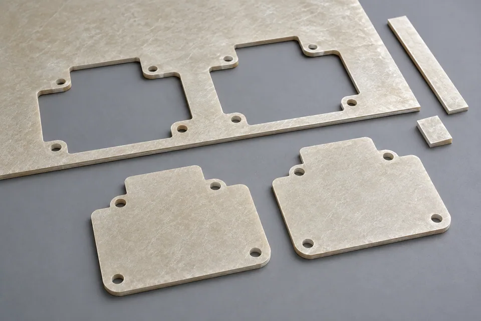
A mica battery barrier with holes, tabs or corner radii needs a profile-cutting trial that examines the whole part, not only its outer outline. The supplied material may be a rigid mica plate or a flexible, reinforced sheet. Internal cutouts can shed flakes or lift a facing as the slug leaves; narrow bridges can crack when the part is released. Define finished geometry and post-cut checks from the buyer’s drawing and material sample. Electrical and thermal performance require separate buyer testing.
Updated
Where This Cutting Application Appears
Start with the installed geometry
Mark the assembly datums and every opening on the mica-barrier drawing. Identify narrow webs between a hole and the outer edge, because a profile that measures correctly overall can still lose a brittle bridge during release.
Control hold-down and stroke
Support rigid mica close to corners and openings, and note which face meets the die or cutting support. For flexible or reinforced mica, check whether hold-down pressure compresses or shifts a layer before the full contour separates.
Inspect after part release
After the outline and internal slugs are removed, inspect hole walls, radii and both faces under the buyer’s agreed method. Record mica flaking, lifted glass-fleece or binder, and any crack that starts at a sharp transition.
Account for matrix removal
Retain the skeleton and removed slugs from the trial. Their breakage or incomplete release can identify an unsupported bridge or ejection problem before loose debris reaches an otherwise acceptable barrier part.
Material-specific acceptance
Inspect both faces and the thickness edge for flakes, binder pullout and layer separation. If the part is used as an electrical barrier, the buyer must define any post-cut dielectric test and edge setback. At holes and narrow bridges, inspect mica flaking and layer lift after slug removal. A sharp-looking outer boundary does not establish integrity around a small internal cutout.
Define the Required Cut Result
- Meet the profile drawing at holes, corners and datums.
- Release parts without tears, trapped cutouts or ejection damage.
- Keep all layers continuous to the specified finished edge.
- Meet the buyer particulate and surface criteria.
- Check the supplied grade for flake release or a lifted mica layer after normal handling.
Problems to Diagnose Before Changing the Knife
A corner tears or rounds beyond the drawing
- Inspect corner support and the blade tip.
- Review the sequence of outside and internal cuts.
- Compare actual part dimensions after release.
A small slug remains attached
- Check die engagement and slug-clearance path.
- Inspect the local support and waste exit.
- Verify that the accepted part is free of trapped fragments.
Parts shift relative to the drawing
- Check sheet registration and hold-down before blade contact.
- Compare first and last parts in the sheet.
- Look for slip or compression during ejection.
Ejector marks appear on an otherwise clean cut
- Separate cutting defects from release damage.
- Review contact area, pressure and matrix takeoff.
- Trial a lower-stress release method approved by the machine owner.
Mica flakes or a facing lifts at the cut
- Inspect the actual sheet construction and identify the layer that separates.
- Compare blade condition, support and cutting direction on matched samples.
- Check whether handling after cutting rather than the blade creates the visible defect.
Knife Forms That May Be Considered
| Possible knife form | When it may be considered | What must be confirmed |
|---|---|---|
| Profile die or shaped knife | For repeat profiles on a compatible die-cutting press. | Confirm outline, die mounting, clearance, hold-down and ejection from drawings and sample parts. |
| Programmable contour blade | For a compatible flexible mica sheet on a controlled-path cutter; a rigid plate needs separate machining feasibility review. | Confirm blade path, tip geometry, support and corner performance on the actual sheet. |
Information to Send for Technical Review
You do not need to know the exact blade name. Send the available workpiece, machine, current-knife and cut-result information so the application can be reviewed against a drawing or sample.
- Mica grade and rigid, flexible or composite construction
- Binder, facing and reinforcement description
- Material thickness and allowable variation
- Permitted loose flakes, edge cracks and delamination
- Approved material sample and finished-part drawing
- Dimensioned part drawing with holes and radii
- Stock orientation, support and hold-down details
- Machine or die mounting drawing
- Part and matrix removal method
- Accepted and rejected profile samples
Questions About This Cutting Application
Why supply the complete barrier profile?
The knife must clear internal holes and narrow bridges as well as the outer contour; those features control where mica can crack.
What should be inspected around a small hole?
Check the opening after slug removal for dimensional error, flakes, layer lift and cracking into the adjacent web.
When is the part ready for acceptance?
Measure and inspect after the same release and collection steps planned for production, since ejection can damage a brittle corner.
Is a matched die always required?
The machine choice depends on grade, shape and volume. Assess a die or compatible programmable cutting method with the actual mica and finished-edge criteria.
Does a sound-looking profile prove barrier function?
No. The buyer must validate electrical and thermal requirements on the specified material and assembly.
What should be sent for contour-tool review?
Provide the mica grade, complete part drawing with holes and bridges, holder or die details, and samples showing permissible edge damage.
Public references and scope
These public sources provide material, cutting-method or safety context for this guide. Supplier pages describe their own materials or equipment; they do not establish a MEIRENTE blade specification or performance claim. Confirm the actual grade, machine setup and required cut with a drawing or sample.
Related product and service information
- Automotive Radar-Absorber Sheet Contour-Cutting Blades - automotive radar-absorber sheet · contour cutting
- Ceramic Battery Insulation Pad Contour-Cutting Blades - ceramic battery insulation pad · contour cutting
- Battery-Pack Flame Barrier Laminate Contour-Cutting Blades - battery-pack flame barrier laminate · contour cutting
Request a Custom Cutting-Knife Review
Send the workpiece details, machine or holder information, current knife photos or sample, required quantity and examples of the present cut problem. Final dimensions, material, edge geometry and tolerances are confirmed from the approved requirements.