
Blade Application Guides / Application Guide / Cable manufacturing
Cable Shielding Laminate Shear Slitting Blades
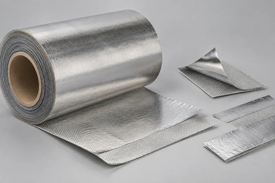
A cable-shielding laminate may combine metal foil, polymer film, conductive adhesive and a removable liner. Shanghai Metal lists AL/PET and AL/PET/AL laminates made for cable shielding and describes foil-laminate slitting equipment. A 3M PET-laminated aluminum shielding tape illustrates an adhesive-backed variant, but not every cable shielding laminate carries conductive adhesive or a liner. Shear slitting converts a wide laminate web into continuous narrow lanes for later wrapping or shielding assembly. It does not make the electrical termination or prove shielding effectiveness. The cutter must part the metal and polymer together; where adhesive is present, its edge must not bridge adjacent lanes. The buyer should identify which face becomes the grounding face, whether the liner stays on and how a slit edge will be handled during cable manufacture. Tool settings and acceptance come from the actual grade and machine trial.
Updated
Where This Cutting Application Appears
Map the shielding lane
Use the cable-wrap drawing to define finished strip width, overlap and any ground-contact area. Mark foil/PET faces and liner travel direction. A lane can be dimensionally correct but wrong-handed for the intended wrap or contact method.
Set both cutting edges
Record upper and lower rotary knife geometry, side clearance, overlap and drive. Trial a material section with its full foil, PET, adhesive and liner stack. Inspect whether the metal folds over the polymer or the backing pulls away under unequal shear.
Look for electrical and visual damage
Check both sides for foil burrs, fractured metal, PET whiskers, adhesive bridges, liner cuts and particles. Where the buyer requires it, measure continuity or surface resistance of the delivered lane using their approved method. A visually clean edge cannot certify shielding in a completed cable.
Recheck after winding and transfer
Separate narrow lanes without adhesive-to-adhesive contact. Inspect roll edges after winding for blocking and foil telescoping; unwind a sample through the buyer’s cable-line path. Distinguish knife damage from cracks introduced by tight wrapping or later guides.
Define the Required Cut Result
- Hold shielding-strip width and wrap overlap.
- Preserve foil and polymer layer integrity at both slit sides.
- Avoid conductive adhesive bridges, metal particles and liner loss.
- Trace face orientation and roll identity into the cable trial.
Problems to Diagnose Before Changing the Knife
Metal foil curls over the polymer edge
- Check knife-pair clearance and lower support.
- Compare incoming laminate bond.
- Inspect both sides of the same slit.
Conductive adhesive bridges lanes
- Inspect knife buildup and liner coverage.
- Review lane separation path.
- Test an early and late cut in one run.
Shield strip cracks during winding
- Compare knife-exit and wound-roll samples.
- Review roll tension and bend radius.
- Locate cracks relative to foil burr or PET peel.
Knife Forms That May Be Considered
| Possible knife form | When it may be considered | What must be confirmed |
|---|---|---|
| Matched circular shear knife pair | For a supported foil/polymer shielding web on a compatible slitter. | Confirm foil burr, polymer peel and adhesive edge on the real laminate. |
| Outside-lane shear trim pair | When a sacrificial margin must be removed before winding useful shielding strips. | Confirm trim collection and retained foil continuity. |
Information to Send for Technical Review
You do not need to know the exact blade name. Send the available workpiece, machine, current-knife and cut-result information so the application can be reviewed against a drawing or sample.
- Shielding product grade and complete layer stack
- Metal and polymer face identification
- Master width, strip schedule and cable-wrap overlap
- Liner and conductive adhesive handling plan
- Upper/lower knife and arbor drawings
- Accepted burr, crack, peel and particle samples
- Winding core, tension and transfer route
- Buyer continuity/grounding and finished-cable test methods
Questions About This Cutting Application
Is PET/aluminum the only cable shielding laminate?
No. Cable foil suppliers list different metal/polymer constructions, including AL/PET/AL; the 3M product is an adhesive-backed example. The buyer must identify its own layers and faces.
Does a clean slit prove EMI performance?
No. Shielding depends on wrap, termination, grounding and final cable design.
Why check conductive adhesive at the edge?
Adhesive transfer can bridge lanes or foul guides even when the metal cut looks clean.
Should the liner be cut?
Only according to the supplied conversion drawing and liner strategy.
When is foil continuity tested?
Use the buyer’s method after conversion and again after representative winding or wrapping if required.
Public references and scope
These public sources provide material, cutting-method or safety context for this guide. Supplier pages describe their own materials or equipment; they do not establish a MEIRENTE blade specification or performance claim. Confirm the actual grade, machine setup and required cut with a drawing or sample.
Related product and service information
- Semiconductive Cable Tape Shear Slitting Blades - semiconductive cable tape · shear slitting
- Wire-Harness Cloth Tape Shear Slitting Blades - wire-harness cloth tape · shear slitting
- Water-Blocking Cable Yarn Transverse Cutting Blades - water-blocking cable yarn · transverse cutting
Request a Custom Cutting-Knife Review
Send the workpiece details, machine or holder information, current knife photos or sample, required quantity and examples of the present cut problem. Final dimensions, material, edge geometry and tolerances are confirmed from the approved requirements.