
Blade Application Guides / Application Guide / Electric vehicle battery manufacturing
Busbar Insulation Laminate Contour-cutting Blades
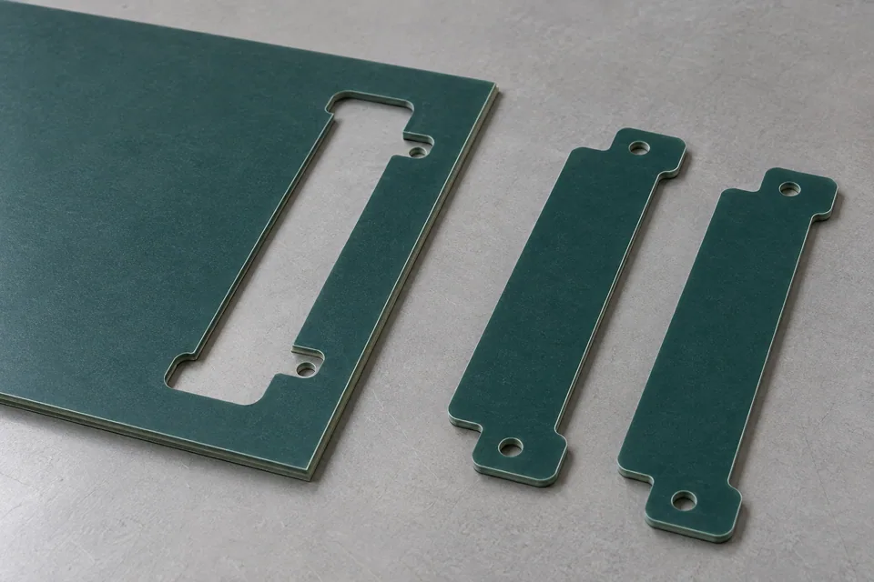
Contour cutting releases a discrete insulation-film shape that follows a busbar conductor layout before the film is laminated to metal. It differs from sheet slitting because the cut follows turns, openings or local reliefs rather than making continuous lanes. Rogers describes flexible adhesive-coated PET and polyimide insulation films used in laminated busbars and the importance of sealing around conductor edges. For a profile trial, identify film side, adhesive side and liner, then compare the cut blank with the conductor drawing and lamination sequence. Tooling selection cannot be inferred from the outline alone because liner handling and heat-activated adhesive behavior vary.
Updated
Where This Cutting Application Appears
Map the insulation perimeter
Trace where the film must extend beyond metal and where holes or contact areas must remain open. Mark datum points shared with conductor tooling so the film does not shift relative to terminals during lamination.
Plan liner and slug removal
Decide whether the release liner should be cut through or remain as a carrier. Every punched hole or internal scrap island needs a removal path that will not contaminate the adhesive. Check exposed adhesive after the blank is lifted.
Control shape distortion
Thin films can stretch during hold-down, pulling a complex perimeter out of register. Compare flat measurements with placement on the actual conductor. Tight inside corners deserve separate inspection for tearing or wrinkling.
Trial after lamination
Review the blank after heat and pressure in the intended assembly process. Confirm insulation coverage and the buyer’s electrical acceptance tests there; a good loose blank is only an intermediate result.
Define the Required Cut Result
- Match the shaped film blank to the approved conductor drawing.
- Keep contacts and openings free while preserving designed insulation overlap.
- Protect adhesive and liner surfaces during cut and release.
- Avoid tears, lifted corners and registration shifts before lamination.
Problems to Diagnose Before Changing the Knife
Blank shifts on the conductor
- Check common datums and liner-release sequence.
- Inspect whether cut strain relaxes after release.
- Review fixture registration during lamination.
Small opening retains a slug
- Check cut-through and local support.
- Review scrap ejection without touching adhesive.
- Inspect surrounding film for tearing.
Inside corner wrinkles
- Compare corner radius and film orientation.
- Check hold-down and pull during release.
- Evaluate fit after actual heat/pressure cycle.
Knife Forms That May Be Considered
| Possible knife form | When it may be considered | What must be confirmed |
|---|---|---|
| Matched profile die | For a repeated blank shape on a compatible press. | Confirm liner strategy, internal slug removal and adhesive condition with real laminate. |
| Programmed contour knife | For prototype profiles or lower-volume design revisions on a compatible table. | Confirm cut depth, hold-down and dimensional stability at tight features. |
Information to Send for Technical Review
You do not need to know the exact blade name. Send the available workpiece, machine, current-knife and cut-result information so the application can be reviewed against a drawing or sample.
- Conductor CAD drawing and approved insulation overlap
- Film, adhesive and release-liner specifications
- Whether the liner is retained or cut through
- Profile, holes, terminals and registration datums
- Acceptable tear, adhesive and surface conditions
- Press or cutting-table interface and part release
- Assembly trial and electrical test owner
Questions About This Cutting Application
Is contour cutting done after the busbar is assembled?
This guide addresses the flexible insulation blank before lamination. An assembled metal busbar requires a separate process assessment.
Can a liner be left intact as a carrier?
That is possible for some constructions, but the cut depth must be trialed against the actual film and liner.
Why test the shaped blank on the conductor?
Local bends, terminal openings and seal overlap cannot be judged fully from a flat profile measurement.
Does this guide set a dielectric clearance?
No. The conductor design and applicable final-assembly qualification set those requirements.
Public references and scope
These public sources provide material, cutting-method or safety context for this guide. Supplier pages describe their own materials or equipment; they do not establish a MEIRENTE blade specification or performance claim. Confirm the actual grade, machine setup and required cut with a drawing or sample.
Related product and service information
- Busbar Insulation Laminate Edge-trimming Blades - busbar insulation laminate · edge trimming
- Mica Battery Barrier Sheet Contour-Cutting Blades - mica battery barrier sheet · contour cutting
- Ceramic Battery Insulation Pad Contour-Cutting Blades - ceramic battery insulation pad · contour cutting
Request a Custom Cutting-Knife Review
Send the workpiece details, machine or holder information, current knife photos or sample, required quantity and examples of the present cut problem. Final dimensions, material, edge geometry and tolerances are confirmed from the approved requirements.