
Blade Application Guides / Application Guide / Electric vehicle battery manufacturing
Battery-Pack Flame Barrier Laminate Contour-Cutting Blades
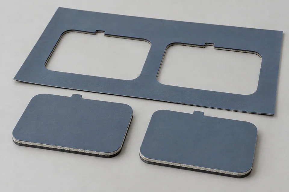
Contour cutting a battery-pack flame-barrier laminate must form a finished shape while severing every actual layer at tabs, slots and corners. LG Chem lists a battery material with laminated inorganic content, and Saint-Gobain shows a mica-and-foam battery pad; their constructions differ. The buyer’s stack-up and liner state determine the trial. Judge the part after internal slugs and matrix are removed, measuring layer alignment as well as the outer outline. A passed cut inspection does not establish a flame rating for the assembled pack.
Updated
Where This Cutting Application Appears
Start with the installed geometry
Put each vent opening, busbar clearance, tab and assembly datum on the buyer drawing. Indicate layer orientation and liner status at cutting, since a face-up and face-down trial can produce different release and edge behavior.
Control hold-down and stroke
Test hold-down around small cutouts without trapping or stretching a soft facing. Verify that the cutting stroke reaches every layer in the buyer stack, including any mica or other inorganic layer, foam, film or liner, instead of leaving a connected hinge at a corner.
Inspect after part release
After slug removal, inspect each supplied layer at the slot wall and outside perimeter. Measure layer recession, lifted faces and any adhesive stringing or loose fibers where those materials are actually present. Use the buyer’s smallest feature as the stress case.
Account for matrix removal
Retain the skeleton and cutout waste to see whether a backing layer stayed attached. Check whether ejection or liner peel shifts a layer or contaminates the usable barrier before acceptance.
Material-specific acceptance
Inspect all constituent layers at slots, tabs and corners after the defined release sequence. A small opening can retain one layer even when the outer profile releases. Check adhesive strings, loose fibers or liner damage only when the buyer’s stack includes those features.
Define the Required Cut Result
- Meet the profile drawing at holes, corners and datums.
- Release parts without tears, trapped cutouts or ejection damage.
- Keep all layers continuous to the specified finished edge.
- Meet the buyer particulate and surface criteria.
- Check the supplied grade for layer offset, uncut backing or delamination after normal handling.
Problems to Diagnose Before Changing the Knife
A corner tears or rounds beyond the drawing
- Inspect corner support and the blade tip.
- Review the sequence of outside and internal cuts.
- Compare actual part dimensions after release.
A small slug remains attached
- Check die engagement and slug-clearance path.
- Inspect the local support and waste exit.
- Verify that the accepted part is free of trapped fragments.
Parts shift relative to the drawing
- Check sheet registration and hold-down before blade contact.
- Compare first and last parts in the sheet.
- Look for slip or compression during ejection.
Ejector marks appear on an otherwise clean cut
- Separate cutting defects from release damage.
- Review contact area, pressure and matrix takeoff.
- Trial a lower-stress release method approved by the machine owner.
One laminate layer extends past another at the edge
- Identify the lagging or stretched layer in a cross-section.
- Inspect blade engagement, support, web tension and layer orientation.
- Compare immediate and post-handling edges for delayed lift.
Knife Forms That May Be Considered
| Possible knife form | When it may be considered | What must be confirmed |
|---|---|---|
| Profile die or shaped knife | For repeat profiles on a compatible die-cutting press. | Confirm outline, die mounting, clearance, hold-down and ejection from drawings and sample parts. |
| Programmable contour blade | For a compatible controlled-path cutter or changing part profiles. | Confirm blade path, tip geometry, support and corner performance on the actual sheet. |
Information to Send for Technical Review
You do not need to know the exact blade name. Send the available workpiece, machine, current-knife and cut-result information so the application can be reviewed against a drawing or sample.
- Layer-by-layer construction, including adhesive and liner
- Total thickness and each layer thickness range
- Which face and orientation must meet the part drawing
- Allowed layer offset, edge lift and particle limits
- Approved material sample and assembly-specific acceptance criteria
- Dimensioned part drawing with holes and radii
- Stock orientation, support and hold-down details
- Machine or die mounting drawing
- Part and matrix removal method
- Accepted and rejected profile samples
Questions About This Cutting Application
Why is a multilayer part drawing necessary?
The accepted part includes openings, tabs, datums and layer orientation, not merely the outside blade shape.
What is checked in a narrow slot?
Confirm all layers are fully severed, the slug leaves cleanly, and no adhesive string or fiber bridge remains.
Should a part be checked before liner removal?
Inspect at the states that matter to the buyer, including after any normal liner peel or matrix removal that could lift a layer.
Can a programmable knife be considered?
Yes, conditionally. Compare it with a die using the actual stack, smallest feature and layer-specific edge acceptance.
Does a correct contour prove flame-barrier performance?
No. Functional claims depend on the material and tested battery assembly.
What is essential for an RFQ?
Send the exact laminate stack, liner orientation, all cutouts and tabs, current cutting support, and accepted layer cross-sections.
Public references and scope
These public sources provide material, cutting-method or safety context for this guide. Supplier pages describe their own materials or equipment; they do not establish a MEIRENTE blade specification or performance claim. Confirm the actual grade, machine setup and required cut with a drawing or sample.
Related product and service information
- Busbar Insulation Laminate Contour-cutting Blades - busbar insulation laminate · contour cutting
- Mica Battery Barrier Sheet Contour-Cutting Blades - mica battery barrier sheet · contour cutting
- Ceramic Battery Insulation Pad Contour-Cutting Blades - ceramic battery insulation pad · contour cutting
Request a Custom Cutting-Knife Review
Send the workpiece details, machine or holder information, current knife photos or sample, required quantity and examples of the present cut problem. Final dimensions, material, edge geometry and tolerances are confirmed from the approved requirements.