
Blade Application Guides / Application Guide / Aerospace composite manufacturing
Aerospace Acoustic Honeycomb Sheet Contour-Cutting Blades
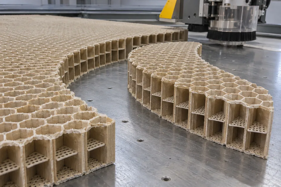
Hexcel’s Acousti-Cap product embeds permeable material within honeycomb cells to create acoustic septa, and the company identifies forming, cutting and machining as processes for the core. A contoured nacelle core therefore has a plausible machining route, but a cutting-tool choice cannot be inferred from the product page alone. Here contour cutting generates a released curved perimeter or internal relief from a core blank, rather than merely cutting a rectangular stock size.
Updated
Where This Cutting Application Appears
Read the three-dimensional core drawing
Identify top and bottom surfaces, installed orientation, wall thickness, curved perimeter and any reliefs. A contour on a thick core may have draft or changing depth; a two-dimensional outline is insufficient if the engineering drawing specifies a profiled edge. Map protected areas where the embedded caps must remain untouched. Program only the geometry released for this exact core grade.
Choose the machining support
Hold the blank so its cells are supported without compressing them. A removable support, sacrificial underlay or approved machining fixture may be needed at tight turns. Evaluate non-metallic and aluminum grades separately, including debris extraction and permitted coolant or dry-process rules. Test the smallest corner and thinnest retained web before considering the whole perimeter.
Check cut-through and cap condition
Inspect the full-depth wall, not just the visible upper face. Tight-radius cuts can tear cell intersections or leave partial wall bridges. Look for cap fragments, displaced septa and chips retained inside adjacent cells. Compare actual relief location with the drawing datum and inspect both entry and exit sides for damage.
Protect downstream bonding and acoustics
Package the core so the fresh perimeter does not shed debris into the bond area. Record dimensional maps and photograph representative cells before skin bonding. The designer specifies flow resistance and cap placement, so final acoustic, structural and bond tests remain with the approved core/assembly process; contour appearance alone cannot certify them.
Plan a difficult-feature coupon
A straight edge sample cannot prove a tight nacelle relief. Build a coupon containing the smallest internal corner, the shortest retained wall and the intended cap arrangement. Inspect the coupon both in its machining fixture and after release, because spring-back can expose damage. Document any permitted edge cleanup, but do not let it change the released profile. Use the same acceptance photographs when evaluating cutter wear or a later core batch.
Define the Required Cut Result
- Create curved perimeter and drawing-defined reliefs in acoustic core.
- Keep nearby cell walls and permeable septa serviceable.
- Maintain through-thickness geometry and orientation.
- Prevent loose debris from entering later bonding.
Problems to Diagnose Before Changing the Knife
Tight curve tears cell intersections
- Increase support around the local feature.
- Review path direction and tool engagement.
- Inspect wall bridges through the core depth.
Cut chips lodge behind caps
- Review extraction and chip size.
- Check cleaning method against material restrictions.
- Inspect cells adjacent to the cut.
Knife Forms That May Be Considered
| Possible knife form | When it may be considered | What must be confirmed |
|---|---|---|
| Programmed core-machining cutter | For a released curved path on a fixtured core blank. | Qualify wall, septum and depth condition for this grade. |
Information to Send for Technical Review
You do not need to know the exact blade name. Send the available workpiece, machine, current-knife and cut-result information so the application can be reviewed against a drawing or sample.
- Released 3D core contour and datum
- Core substrate, thickness, cell size and orientation
- Septum placement and protected cell region
- Fixture and debris-removal specification
- Wall damage and bond-edge acceptance criteria
Questions About This Cutting Application
Why is a drawing more than a 2D silhouette?
The core has thickness, and edge geometry may change through that thickness.
Can a clean upper face hide damage?
Yes. Lower wall tearing and trapped debris require full-depth inspection.
Does contour cutting set flow resistance?
No. Cap design and finished assembly qualification govern that.
Is this for every honeycomb chemistry?
No. Cutter and cleaning must match the specified aluminum or non-metallic core.
Public references and scope
These public sources provide material, cutting-method or safety context for this guide. Supplier pages describe their own materials or equipment; they do not establish a MEIRENTE blade specification or performance claim. Confirm the actual grade, machine setup and required cut with a drawing or sample.
Related product and service information
- Aerospace Acoustic Honeycomb Sheet Cut-To-Size Blades - aerospace acoustic honeycomb sheet · cut to size
- Thermoplastic PEEK Composite Tape Contour Cutting Blades - thermoplastic PEEK composite tape · contour cutting
- Cyanate-Ester Prepreg Contour Cutting Blades - cyanate-ester prepreg · contour cutting
Request a Custom Cutting-Knife Review
Send the workpiece details, machine or holder information, current knife photos or sample, required quantity and examples of the present cut problem. Final dimensions, material, edge geometry and tolerances are confirmed from the approved requirements.