
Blade Application Guides / Application Guide / Advanced solar manufacturing
Solar Interconnect Copper Foil Cross Cutting Blades
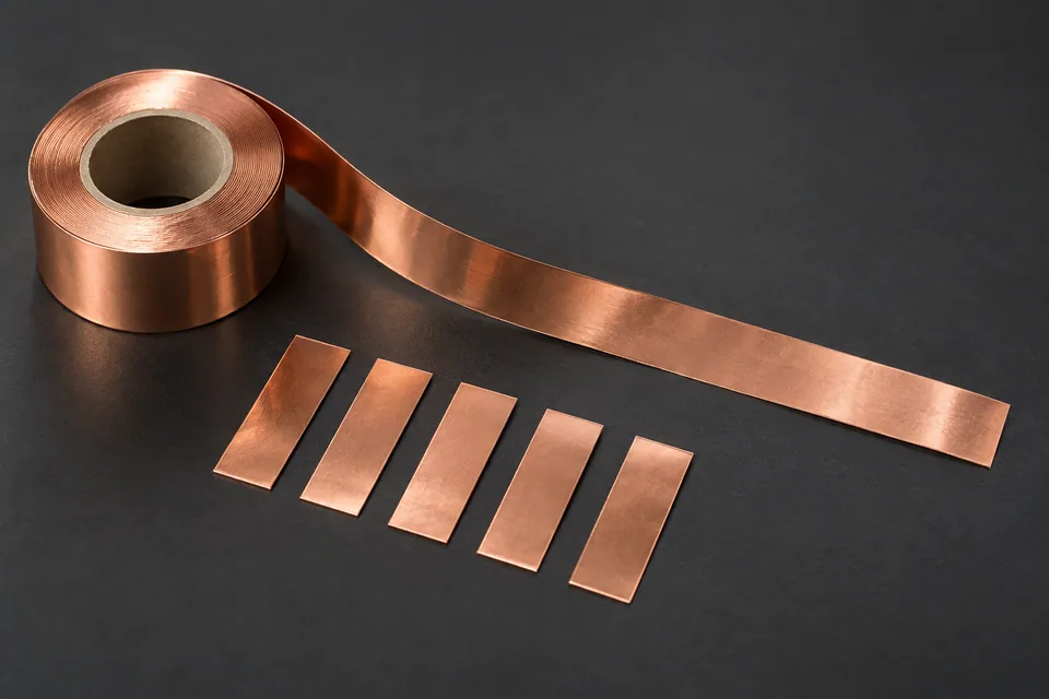
Solar interconnects may use tin-coated copper ribbon, copper foil tape or another buyer-specified conductor construction. For this guide, “copper foil” means the actual flat conductive stock submitted by the buyer; its plating, adhesive or cover layers must be identified rather than assumed. Cross cutting severs the strip across its feed to make finite tabs or lengths. It does not set the strip width, which comes from upstream rolling or longitudinal slitting. Inspect both new end edges for burr, deformation, coating damage and later contact suitability against the module drawing.
Updated
Where This Cutting Application Appears
Define the conductor stack
Record base copper grade, temper, foil thickness, plating or solder coating, adhesive and any PET cover sheet. A blade tested on bare copper cannot automatically qualify a plated laminate.
Set tab or connector length
Use the assembly drawing to place the leading and trailing transverse cuts. Sample relaxed pieces for length and squareness, then examine any bend introduced by the cutting stroke.
Inspect electrically relevant ends
Check both cut ends for raised burrs, smeared coating, loose particles or folded metal that could affect placement or adjacent insulation. Use the buyer’s accepted contact and cosmetic sample rather than a generic burr limit.
Handle finished pieces
Keep conductive faces clean and identify coating side and orientation. Trial placement on the intended module fixture before attributing a later joint defect to the cutter.
Define the Required Cut Result
- Make the specified finite conductor length and square end.
- Meet accepted burr, curl and coating criteria at both ends.
- Preserve clean conductive surfaces during collection.
- Keep pieces compatible with the buyer’s joining or placement step.
Problems to Diagnose Before Changing the Knife
Raised burr appears on one end only
- Check blade/anvil alignment and entry direction.
- Inspect local edge wear.
- Compare bare and plated stock samples.
Tab curls after cutting
- Review support and hold-down pressure.
- Compare stock temper and residual coil set.
- Inspect how the piece leaves the cutter.
Coating chips or smears at the cut
- Identify actual coating and its side.
- Inspect blade condition and cut mode.
- Compare contact-zone acceptance after the buyer’s placement test.
Knife Forms That May Be Considered
| Possible knife form | When it may be considered | What must be confirmed |
|---|---|---|
| Matched shear cross-cut pair | For transverse tab lengths from a continuously fed strip. | Confirm copper/laminate stack, blade condition and accepted end sample. |
| Straight supported cross-cut edge | For intermittent cutting of flat conductor stock. | Confirm hold-down, burr direction, length and part discharge. |
Information to Send for Technical Review
You do not need to know the exact blade name. Send the available workpiece, machine, current-knife and cut-result information so the application can be reviewed against a drawing or sample.
- Copper foil or ribbon specification and temper
- Plating, solder, adhesive and cover-layer map
- Strip width, thickness range and incoming coil condition
- Finished length, squareness and placement drawing
- Accepted end-burr, curl and coating samples
- Cross-cutter and anvil drawings
- Handling and joining sequence
- Actual stock and fixture for trial
Questions About This Cutting Application
Does cross cutting control interconnect strip width?
No. It determines length across the feed. Strip width is set by the incoming stock or a separate longitudinal conversion operation.
Can bare-copper trial results be applied to coated stock?
No. Plating, adhesive and cover layers can alter edge behavior; test the actual stack.
Why inspect both ends?
Burr direction and deformation can differ at entry and exit, while both ends may enter the module assembly.
Does this guide specify an electrical joint design?
No. The buyer supplies the joining method and acceptance; the cutting trial checks the piece delivered to that step.
Public references and scope
These public sources provide material, cutting-method or safety context for this guide. Supplier pages describe their own materials or equipment; they do not establish a MEIRENTE blade specification or performance claim. Confirm the actual grade, machine setup and required cut with a drawing or sample.
Related product and service information
- Solar Interconnect Copper Foil Rotary Die-Cutting Blades - solar interconnect copper foil · rotary die cutting
- Perovskite Solar Barrier Film Cross Cutting Blades - perovskite solar barrier film · cross cutting
- Solar Ribbon Cover Film Cross Cutting Blades - solar ribbon cover film · cross cutting
Request a Custom Cutting-Knife Review
Send the workpiece details, machine or holder information, current knife photos or sample, required quantity and examples of the present cut problem. Final dimensions, material, edge geometry and tolerances are confirmed from the approved requirements.