
Blade Application Guides / Application Guide / Semiconductor assembly
Semiconductor Molding Release Film Cross-Cutting Blades
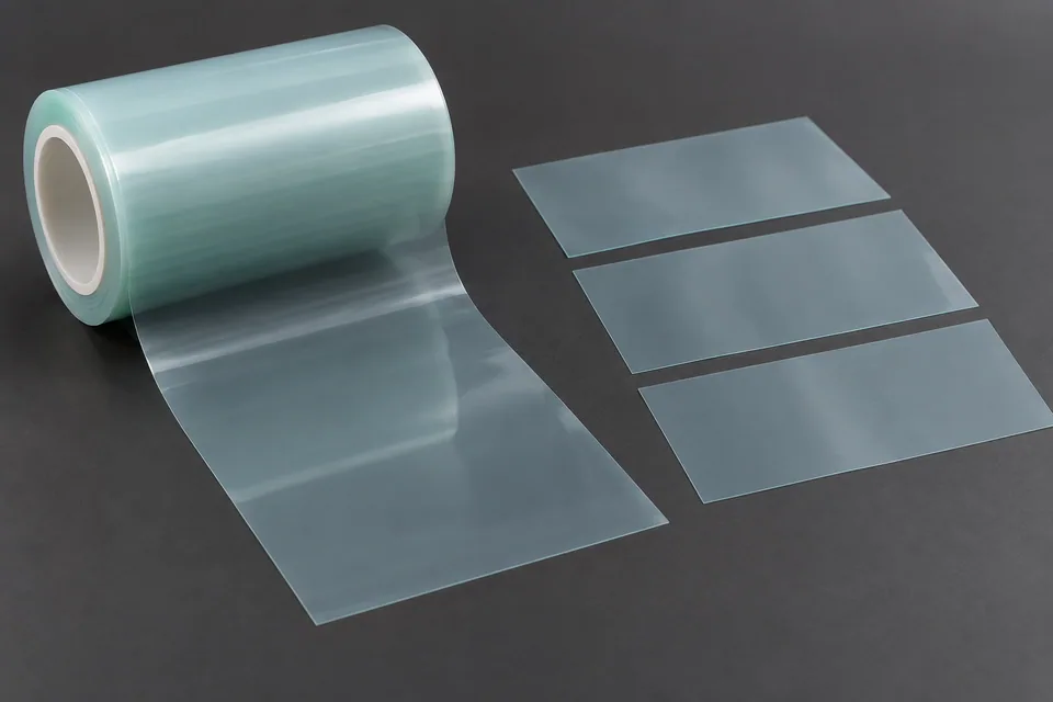
Semiconductor molding release film is used in film-assisted package molding, but grade-specific thickness, surface texture and anti-static treatment can differ. Cross cutting prepares separate lengths or sheets for the molding line; it does not form a package or establish release behavior. Define the mold-related registration and clean-surface requirement from the actual film roll before selecting the cross-cut blade.
Updated
Where This Cutting Application Appears
Cut to mold-film feed length
Use the actual transfer-molding film feed drawing to set the sheet length and leading-edge orientation. Resonac identifies surface texture and antistatic variants, so grade and molding-side face must stay traceable from the parent roll to the cut blank. Measure the cross cut against the feeder datum rather than against an assumed package pitch.
Avoid film wrinkles at the transverse cut
Support the thin release film across the full blade width and observe whether the feed or hold-down pulls it out of plane. A curled leading corner may catch in the mold-film feed path. Compare a fresh cut with a blank after its normal pick-and-place or stacking sequence.
Protect the release surface
Inspect the surface that will face epoxy molding compound for drag marks, impressed particles and edge slivers. If an antistatic grade is specified, keep it segregated and labeled; a blade trial does not demonstrate electrostatic protection or mold release.
Check both ends of each blank
Inspect the leading and trailing transverse edges separately because the severed web and detached sheet can move differently. Check full-width separation, skew and local stretch, then review whether the blank remains flat enough for the customer feeder.
Escalate molding defects separately
Resonac links film design with flash reduction and wrinkle control in transfer molding. Those are material and molding-process outcomes. The cutting trial can document film edge damage and handling, while the package maker must validate flash, release and electrical yield.
Define the Required Cut Result
- Meet the buyer-specified blank length and registration to features.
- Complete the transverse cut without tearing or dragging the workpiece.
- Preserve the specified surface and edge condition on both faces.
- Keep blanks and scrap identified through collection.
- Apply the buyer’s material-specific acceptance plan for semiconductor molding release film.
Problems to Diagnose Before Changing the Knife
Blank length changes during a run
- Measure index distance and web tension before and after the drift.
- Check encoder, nip slip and the cut trigger against registration marks.
- Compare dimensions before and after stacking.
The cut is clean at one side but ragged at the other
- Inspect blade parallelism, support and local pressure across the width.
- Check whether web skew or material thickness varies.
- Compare accepted and rejected edges from the same run.
A blank curls or creases after cutting
- Locate where the defect first appears.
- Review hold-down, takeoff, stacking and any release liner.
- Compare an untouched control from the same lot.
Particles appear on the newly cut edge
- Inspect blade condition and support contact.
- Distinguish cut debris from particles acquired during stacking.
- Apply the buyer inspection method at the point of use.
A release-film edge curls into the next feed path
- Check transverse blade condition and support at the end of the cut.
- Review film tension and takeoff direction.
- Trial the blank through the actual mold-loading path.
Knife Forms That May Be Considered
| Possible knife form | When it may be considered | What must be confirmed |
|---|---|---|
| Cross-cut shear blade set | For transverse sheet or web cutting on a compatible shear station. | Confirm blade length, mounting, engagement and support from the line drawing. |
| Rotary cross-cut knife | For a compatible synchronized rotary cross-cut station. | Confirm cylinder geometry, timing and registration with a production-speed trial. |
Information to Send for Technical Review
You do not need to know the exact blade name. Send the available workpiece, machine, current-knife and cut-result information so the application can be reviewed against a drawing or sample.
- Release-film grade, thickness and surface orientation
- Mold-loading blank dimensions and registration
- Surface mark, sliver and curl limits
- Any anti-static handling requirement set by the buyer
- Web or sheet width, thickness range and feed direction
- Target blank length and registration drawing
- Blade holder, shear or rotary cylinder drawing
- Line speed, indexing and tension records
- Accepted and rejected edge samples
- Takeoff, stacking and waste handling method
Questions About This Cutting Application
How does cross cutting differ from slitting?
Cross cutting separates sheets across web travel. Slitting divides the moving web lengthwise into continuous narrower lanes. Check sheet length and registration versus slit width.
Is overall blank length the only dimension to inspect?
No. Check length, squareness, cut-edge condition, face orientation and registration to the molding feeder datum. Confirm flatness after the normal transfer sequence.
Can a blade be selected from the material name alone?
Request the film grade, thickness, unwind direction, feed drawing and an accepted edge sample before considering a shear or rotary cross-cut setup.
When should the edge be inspected?
Inspect immediately after cutting and after the normal blank-transfer sequence, where a corner can curl, crease or collect particles.
Does a successful cut prove device performance?
No. Cutting approval covers geometry and edge handling only; release, flash control and device yield require the package maker’s molding tests.
Does a clean cross cut prove the film will release from a mold?
No. Release and molding performance belong to the film grade and the validated molding process.
Public references and scope
These public sources provide material, cutting-method or safety context for this guide. Supplier pages describe their own materials or equipment; they do not establish a MEIRENTE blade specification or performance claim. Confirm the actual grade, machine setup and required cut with a drawing or sample.
Related product and service information
- Semiconductor Molding Release Film Rotary Die-Cutting Blades - semiconductor molding release film · rotary die cutting
- UV-Release Wafer Dicing Tape Cross Cutting Blades - UV-release wafer dicing tape · cross cutting
- Leadframe Protective Cover Tape Cross Cutting Blades - leadframe protective cover tape · cross cutting
Request a Custom Cutting-Knife Review
Send the workpiece details, machine or holder information, current knife photos or sample, required quantity and examples of the present cut problem. Final dimensions, material, edge geometry and tolerances are confirmed from the approved requirements.