
Blade Application Guides / Application Guide / Semiconductor assembly
Leadframe Protective Cover Tape Cross Cutting Blades
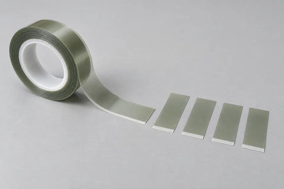
Leadframe production and semiconductor packaging use several distinct protective or masking tapes. A buyer’s “leadframe protective cover tape” must be identified by its exact layer stack and process step before a blade is selected; it should not be assumed to be a particular QFN tape. Cross cutting makes finite lengths from the tape web for placement on a leadframe strip or fixture. The cut should preserve backing, adhesive and liner integrity, avoid particles near bond or mold areas, and keep the piece length registered to the leadframe drawing. Heat and clean-removal performance belong to the specified tape qualification, not the cutting blade alone.
Updated
Where This Cutting Application Appears
Identify the masking step
Confirm whether the tape protects a plated surface, masks a molding area, or supports another package step. Record the leadframe strip dimensions and protected zones; different tapes can share a similar appearance.
Cut to placement pitch
Align the transverse cut with the leadframe strip or fixture datum. Inspect relaxed piece length, leading-edge squareness and whether the tail covers any forbidden bond or mold area.
Preserve the layered tape edge
Inspect adhesive smear, liner lift, backing delamination and particles at both cut ends. Keep the adhesive face protected until the controlled lamination step.
Check later removal
Apply trial pieces using the buyer’s procedure and examine registration, bubbles and clean removal after the specified process exposure. Separate tape-material qualification from cut-induced damage.
Define the Required Cut Result
- Meet the leadframe placement length and alignment drawing.
- Preserve adhesive, backing and liner at both ends.
- Avoid debris or adhesive intrusion into protected process areas.
- Provide pieces that handle and remove as the specified tape process requires.
Problems to Diagnose Before Changing the Knife
Adhesive edge strings near a bond area
- Verify tape grade and adhesive side.
- Inspect blade cleanliness and backing support.
- Compare affected pieces with uncut tape and accepted samples.
Liner lifts during takeoff
- Check cut penetration and release direction.
- Review unwind/collection tension.
- Inspect whether lift grows after storage or handling.
Length passes but the applied tape overlaps a forbidden zone
- Check leadframe datum and placement pitch.
- Measure relaxed versus applied length.
- Compare the current strip drawing with the cutter program.
Knife Forms That May Be Considered
| Possible knife form | When it may be considered | What must be confirmed |
|---|---|---|
| Rotary shear cross-cut pair | For repeated transverse lengths from a moving tape web. | Confirm anvil, registration and adhesive/liner edge on the actual tape. |
| Supported straight cross-cut blade | For intermittent pieces where the tape can be held flat. | Confirm hold-down contact, particle condition and finished length. |
Information to Send for Technical Review
You do not need to know the exact blade name. Send the available workpiece, machine, current-knife and cut-result information so the application can be reviewed against a drawing or sample.
- Exact tape grade and semiconductor process step
- Backing, adhesive, liner and release-side drawing
- Incoming tape width and thickness range
- Leadframe strip drawing and prohibited contact zones
- Required cut length, pitch and squareness
- Accepted edge, particle and clean-removal samples
- Cutter/anvil and collection drawings
- Process exposure and removal test plan
Questions About This Cutting Application
Can any polyimide tape be treated as the same leadframe cover tape?
No. The buyer must specify the qualified tape and its adhesive, liner and process step.
Does cross cutting create the leadframe shape?
No. It prepares finite tape pieces. The metal leadframe geometry is produced in separate operations.
Why inspect both ends of the tape?
Adhesive stringing, liner lift and particle release can differ between leading and trailing edges.
Does this guide promise clean removal after molding?
No. Clean removal is a tape-and-process qualification; the cut trial checks whether the prepared edge introduces defects.
Public references and scope
These public sources provide material, cutting-method or safety context for this guide. Supplier pages describe their own materials or equipment; they do not establish a MEIRENTE blade specification or performance claim. Confirm the actual grade, machine setup and required cut with a drawing or sample.
Related product and service information
- Leadframe Protective Cover Tape Rotary Die-Cutting Blades - leadframe protective cover tape · rotary die cutting
- UV-Release Wafer Dicing Tape Cross Cutting Blades - UV-release wafer dicing tape · cross cutting
- Semiconductor Molding Release Film Cross-Cutting Blades - semiconductor molding release film · cross cutting
Request a Custom Cutting-Knife Review
Send the workpiece details, machine or holder information, current knife photos or sample, required quantity and examples of the present cut problem. Final dimensions, material, edge geometry and tolerances are confirmed from the approved requirements.