
Blade Application Guides / Application Guide / Printing and labels
RFID Paper Label Inlay Edge Trimming Blades: Circuit and Register Control
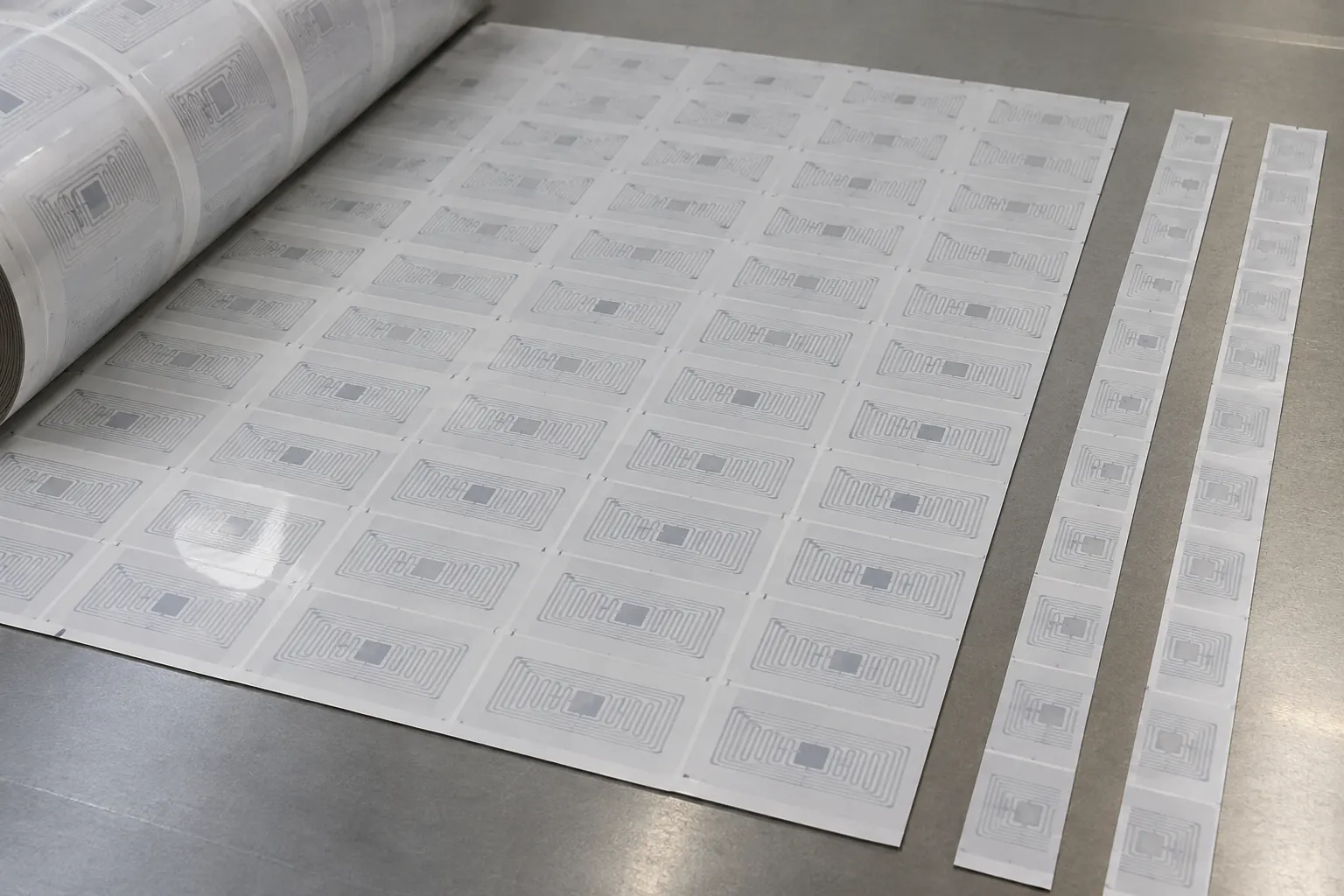
An RFID paper label construction can place a thin antenna and chip-bearing inlay beneath a printable facestock and adhesive layers. The cutting path must be reviewed against the inlay layout and registration system because an apparently minor edge or depth error can affect electrical function, liner integrity or label dispensing.
Updated
Where This Cutting Application Appears
Retail inventory smart labels
Paper RFID labels are converted for item-level identification, where antenna continuity and stable dispensing are checked together. During width edge trimming, irregular or coated outer margins are removed before winding or finishing. Review both retained edges and trim-strip behavior under production tension.
Library and document tracking labels
Thin smart labels are prepared for books, files and assets, requiring unobtrusive edges and protection of the inlay area. During width edge trimming, irregular or coated outer margins are removed before winding or finishing. Review both retained edges and trim-strip behavior under production tension.
Healthcare and logistics identification
Serialized RFID labels are finished for packages and containers, so geometry, readability and adhesive cleanliness must remain consistent. During width edge trimming, irregular or coated outer margins are removed before winding or finishing. Review both retained edges and trim-strip behavior under production tension.
Width Edge Trimming process boundary
Width edge trimming removes controlled side margins to establish parallel finished edges and final web width; it is not a transverse length cut.
Width Edge Trimming setup checkpoint
Define both finished edge positions, centerline control, side guidance, trim width and reliable removal of the two continuous edge strips.
Width Edge Trimming acceptance checkpoint
Measure finished width across the run and inspect parallelism, camber, burr or fray, surface damage and trim-break frequency.
Define the Required Cut Result
- Remove the outer margin while leaving a stable, clean retained edge
- Hold finished web width and edge position within the approved tolerance
- Protect antenna continuity, chip area, adhesive layers and liner
- Deliver converted material accepted for electrical verification, printing and label dispensing
Problems to Diagnose Before Changing the Knife
Antenna nicking or electrical failure
Overlay the approved antenna and chip map with actual cut positions, then compare electrical test results before and after conversion. Do not infer a safe cutting margin without the inlay supplier's dimensional data.
Chip-area pressure or inlay distortion
Review nip and clamping pressure, web support, chip orientation, local thickness change and roll build. Check whether damage occurs at the cut or during winding, stacking or downstream dispensing.
Finished-width drift or unequal side trim
Check web-centering control, sensor position, unwind alignment, trim-holder location, thermal movement and width readings from both retained edges.
Trim-strip breakage, flutter or poor removal
Review trim width, tensile behavior, tension, extraction or winding path, static and the location where the narrow strip first folds or breaks.
Knife Forms That May Be Considered
| Possible knife form | When it may be considered | What must be confirmed |
|---|---|---|
| Circular shear edge-trimming form | Consider where paired rotary edges are already used to retain a controlled web width and carry away narrow trim. | Confirm this form only from the RFID paper label inlay sample, installed equipment interface, operating motion, support condition and approved drawing. |
| Razor edge-trimming form | Consider only when the existing line supports and tensions the web appropriately and the trim strip can be removed safely and consistently. | Confirm this form only from the RFID paper label inlay sample, installed equipment interface, operating motion, support condition and approved drawing. |
Information to Send for Technical Review
You do not need to know the exact blade name. Send the available workpiece, machine, current-knife and cut-result information so the application can be reviewed against a drawing or sample.
- Facestock, adhesive, inlay carrier and liner layer construction
- Antenna outline, chip position and specified keep-clear zones
- Inlay pitch, cross-web lanes and registration-mark details
- Electrical acceptance method and samples from failed positions
- Incoming and required finished web widths plus trim allowance
- Web-guiding method, edge-sensor location and centering tolerance
- Line speed, tension range and trim-strip removal arrangement
- Existing trim-holder interface, cutting motion and setup drawing
Questions About This Cutting Application
How is the safe cut area established for an RFID paper label inlay during width edge trimming?
Use the approved inlay layout, tolerance stack and registration capability to define a keep-clear zone around the antenna and chip. A nominal label outline alone is not sufficient.
Should electrical testing be part of a cutting trial during width edge trimming?
Yes when conversion could approach or load the inlay. Compare representative samples before and after cutting and record failures by lane and web position so electrical damage is not confused with incoming defects.
Why can one retained edge look different from the other during width edge trimming?
Cross-web thickness, coating orientation, web steering, holder alignment and trim-strip tension may differ by side. Photograph and measure both edges separately.
What makes a narrow trim strip unstable during width edge trimming?
Low tensile strength, tack, static, excessive free span, airflow and inconsistent trim width can cause flutter or breaks. Review the complete removal path with the cut.
Can edge-trimming geometry be chosen from finished width alone during width edge trimming?
No. The existing motion, holder, overlap or penetration, web support and trim disposal arrangement must be confirmed from equipment data and an approved drawing.
Related product and service information
- Self-Adhesive Labelstock Edge-Trimming Blades - self-adhesive labelstock · width edge trimming
- RFID Paper Label Inlay Roll Slitting Blades: Circuit and Register Control - RFID paper label inlay · roll slitting
- Security Paper Label Stock Edge Trimming Blades: Feature and Liner Protection - security paper label stock · width edge trimming
Request a Custom Cutting-Knife Review
Send the workpiece details, machine or holder information, current knife photos or sample, required quantity and examples of the present cut problem. Final dimensions, material, edge geometry and tolerances are confirmed from the approved requirements.