
Blade Application Guides / Application Guide / Molded fiber packaging
Molded Fiber Tray Inline Trimming and Die-Cutting Blades
Molded fiber tray inline trimming blades remove process flanges and create finished perimeters or openings after formed fiber parts are pressed. Unlike flat pulp-sheet cutting, the workpiece is three-dimensional and can vary in moisture, wall thickness and rim support. Review should define the part datum, nesting fixture, profile, coating, edge requirement, ejection and scrap path.
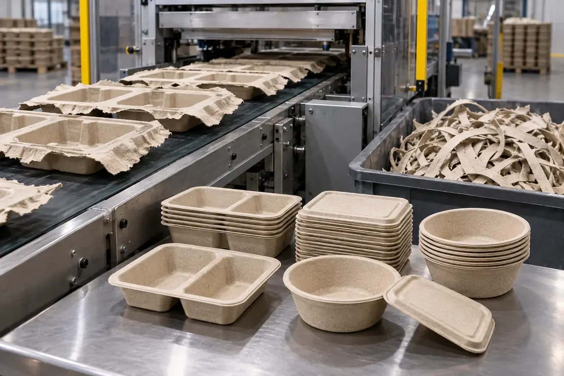
Where This Cutting Application Appears
Food-tray perimeter finishing
Process flanges are removed while preserving the functional rim and nesting geometry.
Fiber lid and bowl trimming
Round or shaped parts are cut to the approved closure interface.
Assembly-feature preparation
Holes, slots or local features are cut in supported molded parts.
Common Ways to Describe This Cutting Problem
- molded fiber tray inline trimming blades
- natural fiber packaging die-cutting knife
- molded pulp tray rim trimming tooling
- fiber bowl perimeter cutting blades
- formed paper lid punching knife
- molded fiber flange removal die
- pulp packaging trim press blades
- custom molded fiber part cutting tooling
Define the Required Cut Result
- Finished perimeter registered to the formed-part datum.
- Clean edges without excessive fuzz, tearing or loose fragments.
- Supported rims and walls without crushing or cracking.
- Reliable ejection and scrap removal without contaminating packaging.
Problems to Diagnose Before Changing the Knife
Trim profile shifts relative to the tray
- Define datum and locating surfaces in the fixture.
- Measure formed variation before and after trimming.
- Inspect moisture, warpage and nesting position.
Fiber fuzz or torn layers remain at the rim
- Identify furnish, forming method and barrier coating.
- Map defects against thick sections and corners.
- Compare support and moisture for accepted and rejected parts.
Tray rim or sidewall crushes
- Review fixture contact, rim support and hold-down.
- Inspect wall thickness and stiffness near damage.
- Determine whether distortion occurs in cutting, ejection or stripping.
Trim scrap remains attached or blocks ejection
- Map connected fibers and bridges around the profile.
- Review cutting sequence, stripper motion and scrap path.
- Check whether coating or moisture changes release.
Knife Forms That May Be Considered
| Possible knife form | When it may be considered | What must be confirmed |
|---|---|---|
| Matched trim punch-and-die arrangement | For formed parts located in a dedicated nest. | Part drawing, datum, nest, press interface, ejection and scrap removal. |
| Steel-rule profile die arrangement | For compatible formed-fiber profiles with supported perimeter cutting. | Part support, wall and flange, radii, cutting base, coating and sample. |
| Compound perimeter-and-feature cutting arrangement | When outer trim and openings require a controlled relationship. | Feature datums, sequence, support, slug retention, ejection and inspection. |
Information to Send for Technical Review
You do not need to know the exact blade name. Send the available workpiece, machine, current-knife and cut-result information so the application can be reviewed against a drawing or sample.
- Fiber furnish, forming process and representative parts.
- Moisture, wall and flange construction and coatings.
- Finished-part drawing with trim datum and revision.
- Untrimmed and accepted parts showing location relationship.
- Press or inline station, interface, nest and support.
- Hold-down, ejection, slug retention and scrap sequence.
- Edge, cleanliness, dimensional and function inspection.
- Production expectation, changeover and trial quantity.
Questions About This Cutting Application
How does this differ from flat pulp-sheet cutting?
The formed part needs three-dimensional location and support.
Why is an untrimmed part needed?
It shows the flange, locating surfaces, variation and support requirement.
Should barrier coating be identified?
Yes; it can affect edge integrity, cleanliness and scrap release.
What can crush a tray rim?
Possible factors include support, hold-down, wall variation, moisture and ejection.
Can tooling be defined from the finished outline alone?
No; untrimmed geometry, nest, press interface and scrap path are required.
Request a Custom Cutting-Knife Review
Send the workpiece details, machine or holder information, current knife photos or sample, required quantity and examples of the present cut problem. Final dimensions, material, edge geometry and tolerances are confirmed from the approved requirements.