
Blade Application Guides / Application Guide / Semiconductor assembly
Conductive Chip-Tray Sheet Cross-Cutting Blades
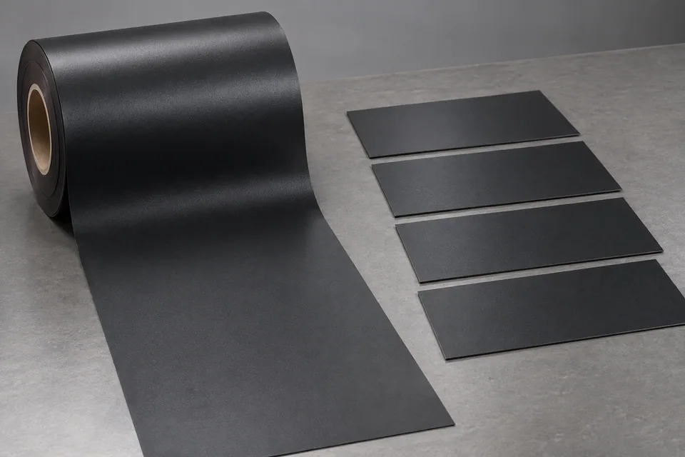
Conductive chip-tray sheet is a thermoplastic stock that may be thermoformed into electronics or semiconductor handling trays. Suppliers describe conductive high-impact polystyrene roll stock and finished conductive trays, but the buyer must identify the actual resin and conductive treatment. Cross cutting here produces flat rectangular blanks from a roll or large sheet before forming, not the shaped tray cavities. Set length, width and forming-feed margin from the mold layout. Inspect burr, dust and curl before the blank enters the forming tool. Electrical protection is confirmed on the final tray by the buyer’s method.
Updated
Where This Cutting Application Appears
Work backward from the forming layout
Use the thermoforming tool drawing to establish blank length, width and clamp margin. Mark machine direction and any surface or conductive coating orientation so the cut blank can be placed consistently in the mold.
Separate the relatively stiff sheet
Compare the installed cross-knife and anvil with the actual resin and thickness. Support the sheet across its width to avoid a diagonal cut or cracked corner; record blade penetration and inspect whether a hanging sliver remains at the far edge.
Check the blank before heating
Measure length and squareness after the sheet relaxes. Inspect both faces for scratches and plastic dust, and verify that clamp edges are free of burrs that could snag or shed particles in the forming station.
Trace formed-tray defects upstream
Form representative cut blanks and compare cavities with an uncut control from the same lot. If registration or conductivity fails in the finished tray, identify whether the issue came from blank geometry, material distribution or thermoforming rather than claiming the cross cut decides it.
Define the Required Cut Result
- Provide rectangular blanks that fit the forming clamp.
- Meet buyer length, squareness and edge-cleanliness limits.
- Avoid cracked corners, slivers and surface scratching.
- Preserve orientation and lot traceability for final tray tests.
Problems to Diagnose Before Changing the Knife
Blank corner cracks during cut
- Check actual resin and sheet thickness.
- Review support at the far side of the blade.
- Inspect blade wear and compare feed direction.
Formed tray is misregistered
- Measure blank squareness and clamp margin.
- Check forming alignment separately.
- Confirm correct orientation of cut blanks.
Black particles appear at the cut
- Inspect blade and anvil wear.
- Compare with incoming carbon-filled stock.
- Review collection and cleaning before forming.
Knife Forms That May Be Considered
| Possible knife form | When it may be considered | What must be confirmed |
|---|---|---|
| Full-width straight cross knife | For flat sheet stock with suitable anvil and hold-down. | Confirm complete cut, squareness, no slivers and stable feeding. |
| Indexed sheet cross cutter | Where the line feeds set lengths to a thermoforming process. | Confirm clamp-margin repeatability and sample blanks after handling. |
Information to Send for Technical Review
You do not need to know the exact blade name. Send the available workpiece, machine, current-knife and cut-result information so the application can be reviewed against a drawing or sample.
- Exact conductive sheet resin and supplier data
- Bulk-filled versus coated conductive construction
- Sheet thickness and roll or parent dimensions
- Mold layout, clamp margin and blank size
- Machine direction and face orientation
- Accepted burr, particle and scratch limits
- Cross knife, anvil and feed drawings
- Final formed-tray ESD test required by buyer
Questions About This Cutting Application
Is the cross-cut blank already a chip tray?
No. It is flat stock sized for later forming; cavities and final tray properties are assessed after thermoforming.
Why preserve sheet orientation?
Forming registration and any face-specific treatment may depend on which side and direction enter the tool.
Does cutting maintain a specified resistance class?
It cannot establish that alone. The buyer must measure the actual formed tray under its applicable ESD method.
What edge problems affect the forming step?
Cracked corners, hanging slivers and plastic dust can interfere with clamping or contaminate the tool.
What should be sent for a knife trial?
Send the actual conductive sheet, blank drawing with clamp margin, cross-cutter details and formed-tray acceptance plan.
Public references and scope
These public sources provide material, cutting-method or safety context for this guide. Supplier pages describe their own materials or equipment; they do not establish a MEIRENTE blade specification or performance claim. Confirm the actual grade, machine setup and required cut with a drawing or sample.
Related product and service information
- Conductive Chip-Tray Sheet Rotary Die-Cutting Blades - conductive chip-tray sheet · rotary die cutting
- UV-Release Wafer Dicing Tape Cross Cutting Blades - UV-release wafer dicing tape · cross cutting
- Leadframe Protective Cover Tape Cross Cutting Blades - leadframe protective cover tape · cross cutting
Request a Custom Cutting-Knife Review
Send the workpiece details, machine or holder information, current knife photos or sample, required quantity and examples of the present cut problem. Final dimensions, material, edge geometry and tolerances are confirmed from the approved requirements.