
Blade Application Guides / Application Guide / Pharmaceutical packaging materials
Blister Lidding Foil Cutting Without Wrinkle Damage
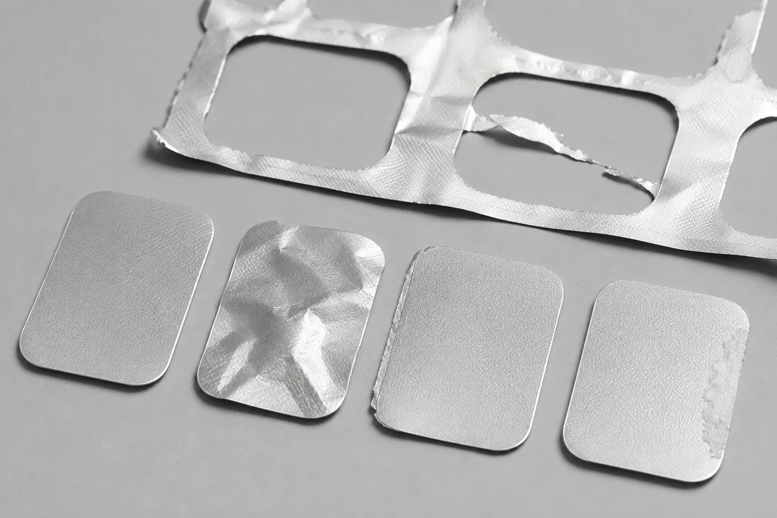
Blister lidding foil may be supplied as reel stock or converted into defined lid shapes, and its aluminum substrate, print, primer, and heat-seal coating each influence the cut. A sound review separates profile-cutting defects from sealing performance and uses the approved foil construction, tool interface, orientation, and inspection method.
Where This Cutting Application Appears
Precut lids for individual blister formats
Printed or plain lidding foil is cut to an approved outline, with corner radii, tabs, and orientation controlled to the packaging drawing.
Registered cutting of printed lid arrays
Repeated graphics are aligned to the cutting profile so essential printed zones remain within the dimensional and positional limits specified by the purchaser.
Foil blanking with scrap-skeleton removal
Multiple lid shapes are separated from a web while the surrounding matrix stays strong enough for consistent stripping and collection.
Common Ways to Describe This Cutting Problem
- blister lidding foil profile cutting
- lidding foil wrinkle during die cutting
- blister foil edge burr problem
- printed lidding foil profile registration
- heat seal lacquer buildup on cutting tool
- blister lid scrap skeleton tearing
- precut blister foil lid dimensions
- how to inspect cut lidding foil edges
Define the Required Cut Result
- Produce the specified lid outline without crushing corners or distorting pull tabs
- Limit aluminum burrs and coating fragments on every cut perimeter
- Keep the foil flat through registration, blanking, and part discharge
- Release the scrap skeleton without tearing it into uncontrolled fragments
Problems to Diagnose Before Changing the Knife
Thin foil wrinkles around a corner or narrow tab
Review hold-down distribution, profile radii, cutting sequence, foil tension, support flatness, clearance, local coating build, and part-release direction.
A raised burr appears on one face of the aluminum edge
Map burr direction against foil temper and gauge, tool clearance, penetration, wear, alignment, substrate support, and printed-face orientation.
Heat-seal lacquer or print coating accumulates near the profile
Check coating type and cure, surface temperature, tool finish, cutting pressure, cleaning method, run length, and whether pickup begins at one geometry feature.
The waste matrix tears before it reaches collection
Examine bridge width, nest layout, corner shape, foil direction, web tension, coating cracks, stripping angle, static, and the distance to the waste take-up.
Knife Forms That May Be Considered
| Possible knife form | When it may be considered | What must be confirmed |
|---|---|---|
| Matched profile punch and die | Consider for repeatable precut lid geometry where the equipment controls registration, support, stripping, and part discharge. | Confirm approved profile, corner radii, tab details, clearance, foil orientation, mounting interface, ejection method, and dimensional inspection plan. |
| Steel-rule or flatbed profile cutting | Consider where the converter uses a supported intermittent process for defined foil or foil-laminate shapes. | Confirm rule specification, backing, make-ready, cutting pressure, registration system, stack or single-web condition, and production foil trials. |
Information to Send for Technical Review
You do not need to know the exact blade name. Send the available workpiece, machine, current-knife and cut-result information so the application can be reviewed against a drawing or sample.
- Approved lidding-foil structure, aluminum gauge and temper, coatings, and printed-face orientation
- Purchaser-supplied packaging specification plus required handling, cleanliness, and traceability controls
- Dimensioned lid drawing with radii, tabs, perforations if any, and profile tolerances
- Print repeat, registration datum, allowable print-to-cut variation, and web travel direction
- Cutting method, stroke rate, support, hold-down, stripping path, and equipment interface drawing
- Part and scrap discharge arrangement, nest layout, matrix bridge widths, and collection method
- Burr, wrinkle, coating-chip, and dimensional inspection methods with accepted reference samples
- Production foil samples, defect images marked by face and direction, and current tool condition
Questions About This Cutting Application
Does a clean cut edge prove that a blister lid will seal correctly?
No. Edge quality is one conversion result. Seal performance depends on the approved foil, blister material, process settings, contact conditions, and the purchaser's validation plan.
Why do wrinkles concentrate around a pull tab?
A narrow tab changes material flow and hold-down support. Clearance, profile radii, cutting order, foil tension, coating build, and release direction should be reviewed around that feature.
How should lidding-foil burr direction be documented?
Mark print and seal faces, feed direction, tool and support sides, then record the inspection method and exact profile location where the burr is measured.
What helps keep a foil scrap skeleton continuous?
Adequate bridge geometry, stable web tension, smooth stripping angles, consistent cutting depth, and a matrix path suited to the foil construction all matter.
Can a drawing alone define a replacement profile tool?
The profile drawing is necessary but insufficient. Mounting, clearance, stroke, support, registration, discharge, foil stack, and accepted sample must also be confirmed.
Request a Custom Cutting-Knife Review
Send the workpiece details, machine or holder information, current knife photos or sample, required quantity and examples of the present cut problem. Final dimensions, material, edge geometry and tolerances are confirmed from the approved requirements.