
Blade Application Guides / Application Guide / Energy storage manufacturing
AGM Battery Separator Mat Contour-Cutting Blades
An AGM separator mat can be cut into shaped pads, but a good outline is only one part of acceptance. The glass or glass-synthetic network is compressible, so pressure from a die or hold-down can change thickness and leave fibers at a corner even when the nominal tool path is correct. Microporous documents different AGM constructions and compression integrity; the customer must define the grade and measurement condition for this part. Use a dimensioned profile, identify narrow bridges and internal cutouts, then inspect the released pad and the surrounding matrix after the normal recovery interval.
Updated
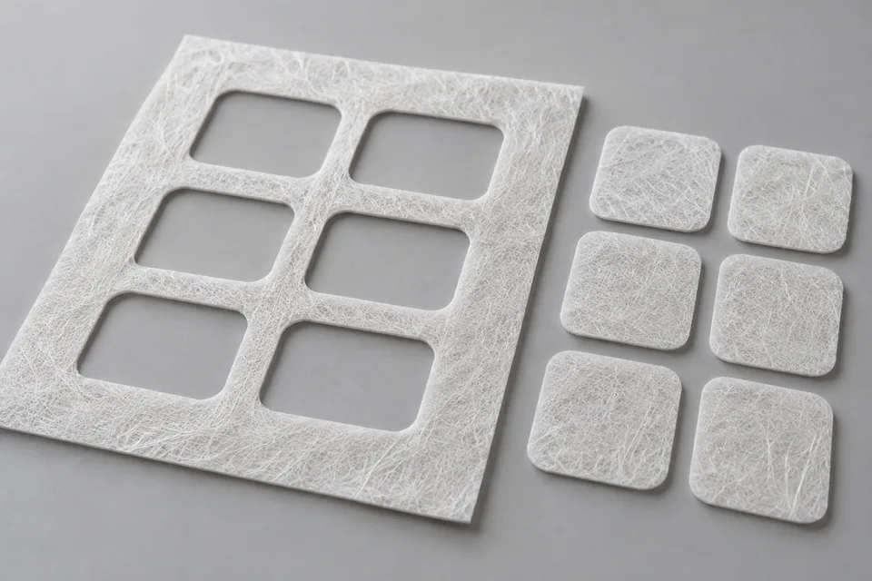
Where This Cutting Application Appears
Locate fragile features on the drawing
Mark small holes, narrow tabs and inside radii. Ask the buyer which features are function-critical and where loose glass fibers are unacceptable. Keep an approved finished pad beside trial parts for comparison.
Set hold-down without flattening the mat
Record the pressure and support used by the die or path cutter. Compare a cut pad with an uncut control after both have had the same handling and recovery time; a sharp tool alone cannot correct excessive compression.
Follow the part out of the matrix
Watch whether cutouts stay attached, tear away or shed fibers as the pad is lifted. Note ejection contact and the order in which waste is removed. Inspect the underside as well as the visible top contour.
Measure the released profile
Measure dimensions in the buyer’s stated condition and check compressed thickness separately. Look for rounded corners, torn bridges and loose fibers after the part is packed or transferred.
Match the tool to the machine
A shaped die is useful for repeat profiles on a suitable press; a programmable blade may suit changing patterns. Compare either option against machine drawings, sample stock and the actual release method.
Define the Required Cut Result
- Meet the finished AGM profile drawing after release and recovery.
- Protect narrow bridges and internal corners from tearing.
- Keep loose fibers and retained cutouts within buyer limits.
- Preserve accepted thickness under the specified compression method.
Problems to Diagnose Before Changing the Knife
Corners tear when the pad is removed
- Check whether the tear begins during cutting or matrix stripping.
- Compare hold-down force and blade condition at the same feature.
- Review the release direction and small bridge geometry.
A cutout remains in the accepted part
- Trace the ejection and waste-removal step.
- Inspect the underside for partially separated fibers.
- Compare the result with the buyer’s particle criterion.
Profile measures short after release
- Use the agreed measurement load and recovery time.
- Check sheet registration and compression during die closure.
- Compare first and last parts from the same trial lot.
The mat surface shows a pressure mark
- Locate die, hold-down or ejector contact.
- Compare compressed thickness with an uncut control.
- Trial a different support or release sequence before altering the drawing.
Knife Forms That May Be Considered
| Possible knife form | When it may be considered | What must be confirmed |
|---|---|---|
| Profile die or shaped knife | For repeated AGM contours on a press with controlled mat support and part ejection. | Check profile, mounting, closure, hold-down and release against machine drawings and accepted pads. |
| Programmable contour blade | For a compatible flatbed cutter or variable shapes where mat movement can be controlled. | Trial corner path, support and fiber pullout at the actual mat thickness and grade. |
Information to Send for Technical Review
You do not need to know the exact blade name. Send the available workpiece, machine, current-knife and cut-result information so the application can be reviewed against a drawing or sample.
- AGM fiber blend, grade and grammage
- Finished profile and critical-feature drawing
- Compressed-thickness test and recovery time
- Accepted loose-fiber and puncture criteria
- Die or flatbed machine drawing
- Hold-down and ejection method
- Matrix and internal-cutout removal plan
- Accepted finished sample
Questions About This Cutting Application
Why compare the released pad with the matrix?
The matrix can reveal tearing and incomplete internal cuts that are hidden when only the finished outline is viewed.
When should profile dimensions be taken?
Use the buyer’s specified contact pressure and recovery interval after normal part release.
Can a harder die eliminate fiber pullout?
Not by itself. Support, closure, edge condition and part removal can all affect fiber loss.
Is a programmable blade always preferable for AGM?
No. Machine stability, profile volume, cut quality and handling determine whether a flatbed cutter or press die is appropriate.
What must be checked at internal openings?
Confirm full separation, removal of cutouts, clean bridge edges and no trapped fiber fragments.
Public references and scope
These public sources provide material, cutting-method or safety context for this guide. Supplier pages describe their own materials or equipment; they do not establish a MEIRENTE blade specification or performance claim. Confirm the actual grade, machine setup and required cut with a drawing or sample.
Related product and service information
- Vanadium Redox-Flow Membrane Contour-Cutting Blades - vanadium redox-flow membrane · contour cutting
- Zinc-Air Battery Separator Paper Contour-Cutting Blades - zinc-air battery separator paper · contour cutting
- Oxide Solid-Electrolyte Green Tape Contour-Cutting Blades - oxide solid-electrolyte green tape · contour cutting
Request a Custom Cutting-Knife Review
Send the workpiece details, machine or holder information, current knife photos or sample, required quantity and examples of the present cut problem. Final dimensions, material, edge geometry and tolerances are confirmed from the approved requirements.