
Blade Application Guides / Application Guide / Printed electronics
RFID Aluminum Antenna Laminate Cross-Cutting Blades
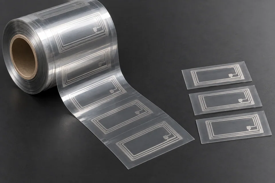
An RFID aluminum antenna laminate can contain an aluminum conductor pattern on a polymer or paper substrate, with adhesive, face film, liner and a chip depending on the inlay construction. Cross cutting indexes between repeating antenna units to make separate lengths or labels. The first requirement is the no-cut zone around the actual antenna and chip; the finished blank length alone does not protect the circuit.
Updated
Where This Cutting Application Appears
Index between antenna repeats
Identiv documents PET with an etched aluminum antenna, acrylic adhesive and chip, supplied as dry or wet inlays on reels. Set the transverse cut in the approved gap between repeating inlay units, using a printed mark or another verified datum. A nominal blank length cannot substitute for chip and antenna clearance.
Preserve chip and conductor zones
Map the aluminum trace, chip attachment and any adhesive window before tooling. Keep the cutting edge outside those features. A strike through a conductor can produce an open circuit even when the finished piece has the correct outside dimensions.
Control layered-web separation
Check whether the conversion stage includes a liner or added face film, because dry and wet inlays differ. Inspect for metal slivers, adhesive stringing, PET stretch and interlayer shift at each transverse edge. Do not assume one depth setting fits both constructions.
Separate mechanical and RF checks
Measure registration from the cut to the antenna and chip on several consecutive repeats. Then ask the inlay owner to perform its normal electrical or RF screen on cut samples; Identiv reports electrical inspection for its inlays, but a knife maker cannot certify read performance.
Stack without damaging components
Keep finished pieces oriented so a cut edge or adhesive surface does not scrape a neighboring chip. Inspect the first and last pieces after collection for bent antenna laminate or blocking before accepting the cutter layout.
Define the Required Cut Result
- Meet the buyer-specified blank length and registration to features.
- Complete the transverse cut without tearing or dragging the workpiece.
- Preserve the specified surface and edge condition on both faces.
- Keep blanks and scrap identified through collection.
- Apply the buyer’s material-specific acceptance plan for RFID aluminum antenna laminate.
Problems to Diagnose Before Changing the Knife
Blank length changes during a run
- Measure index distance and web tension before and after the drift.
- Check encoder, nip slip and the cut trigger against registration marks.
- Compare dimensions before and after stacking.
The cut is clean at one side but ragged at the other
- Inspect blade parallelism, support and local pressure across the width.
- Check whether web skew or material thickness varies.
- Compare accepted and rejected edges from the same run.
A blank curls or creases after cutting
- Locate where the defect first appears.
- Review hold-down, takeoff, stacking and any release liner.
- Compare an untouched control from the same lot.
Particles appear on the newly cut edge
- Inspect blade condition and support contact.
- Distinguish cut debris from particles acquired during stacking.
- Apply the buyer inspection method at the point of use.
The transverse cut clips an antenna or chip clearance zone
- Compare actual cut position with registration marks and the repeat pitch.
- Inspect web stretch, sensor timing and nip slip.
- Recheck the no-cut window from the buyer artwork rather than moving the blade by eye.
Knife Forms That May Be Considered
| Possible knife form | When it may be considered | What must be confirmed |
|---|---|---|
| Cross-cut shear blade set | For transverse sheet or web cutting on a compatible shear station. | Confirm blade length, mounting, engagement and support from the line drawing. |
| Rotary cross-cut knife | For a compatible synchronized rotary cross-cut station. | Confirm cylinder geometry, timing and registration with a production-speed trial. |
Information to Send for Technical Review
You do not need to know the exact blade name. Send the available workpiece, machine, current-knife and cut-result information so the application can be reviewed against a drawing or sample.
- Antenna artwork, repeat pitch and chip keep-out zone
- Laminate stack including substrate, adhesive and liner
- Registration marks and cut-position tolerance
- Electrical test ownership and accepted edge samples
- Web or sheet width, thickness range and feed direction
- Target blank length and registration drawing
- Blade holder, shear or rotary cylinder drawing
- Line speed, indexing and tension records
- Accepted and rejected edge samples
- Takeoff, stacking and waste handling method
Questions About This Cutting Application
How does cross cutting differ from slitting?
Cross cutting separates sheets across web travel. Slitting divides the moving web lengthwise into continuous narrower lanes. Check sheet length and registration versus slit width.
Is overall blank length the only dimension to inspect?
No. Check the transverse cut against the antenna repeat, trace clearance, finished width and any liner or adhesive damage on the actual inlay.
Can a blade be selected from the material name alone?
Provide the antenna repeat drawing, chip location, registration method and dry/wet layer stack before choosing the cutter arrangement.
When should the edge be inspected?
Inspect at the cutter for metal or PET debris and again after stacking, where an edge or chip may abrade another piece.
Does a successful cut prove device performance?
No. Follow dimensional inspection with the inlay manufacturer’s electrical or RF test; visual edge quality cannot prove antenna function.
Can antenna function be approved from visual cut quality?
No. A finished inlay needs the device maker’s electrical or RF test as well as dimensional inspection.
Public references and scope
These public sources provide material, cutting-method or safety context for this guide. Supplier pages describe their own materials or equipment; they do not establish a MEIRENTE blade specification or performance claim. Confirm the actual grade, machine setup and required cut with a drawing or sample.
Related product and service information
- RFID Aluminum Antenna Laminate Rotary Die-Cutting Blades - RFID aluminum antenna laminate · rotary die cutting
- Printed Battery Current-Collector Film Cross-Cutting Blades - printed battery current-collector film · cross cutting
- Membrane-Switch Spacer Film Cross-Cutting Blades - membrane-switch spacer film · cross cutting
Request a Custom Cutting-Knife Review
Send the workpiece details, machine or holder information, current knife photos or sample, required quantity and examples of the present cut problem. Final dimensions, material, edge geometry and tolerances are confirmed from the approved requirements.