
Blade Application Guides / Application Guide / Specialty metal converting
Magnesium Alloy Foil Precision Blanking Blades
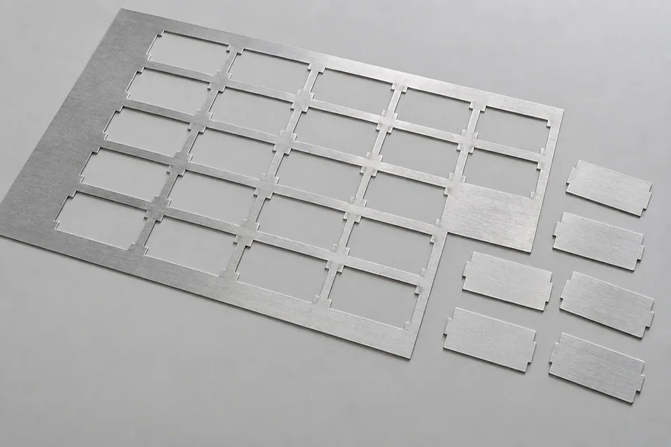
Precision blanking here means cutting separate, enclosed profiles from magnesium alloy foil. It is a different operation from longitudinal coil slitting: the press must register the profile, support the thin web, separate each blank and release the surrounding skeleton. Before a punch and die are specified, identify the actual alloy and temper, foil thickness range, profile drawing and permitted burr. A trial with the buyer’s stock should show that the blank remains flat and that ejection does not scar its face or corners.
Updated
Where This Cutting Application Appears
Registered profile, not a slit strip
Use the datum scheme on the part drawing to check each enclosed blank. Compare edge position, small radii and corners on first and later strokes; progressive feeding can hide registration drift. Retain both the finished blank and skeleton from the trial.
Foil restraint at the cut
Review feed support, hold-down and stripper contact before interpreting a curled edge as a knife problem. Thin foil can move with the punch or crease while it is stripped. Inspect both faces and map marks to the press contact points.
Punch-to-die fit and edge acceptance
Measure clearance and alignment around the entire contour, especially tight corners. Burr, rollover and cut-face shape must be judged against approved samples, not a universal clearance rule. Record the tooling condition and setup that produced an accepted part.
Blank, skeleton and fines route
Document how small blanks leave the die and how the skeleton and any fines are collected. Review the site’s material-specific fire and dust controls before a production trial involving magnesium-containing trim or particles.
Define the Required Cut Result
- Hold the enclosed profile to the buyer’s drawing and inspection method.
- Keep blanks flat and free of ejection or hold-down marks.
- Meet agreed burr and corner-integrity limits on the full perimeter.
- Remove blanks and skeleton reliably without generating an uncontrolled fines path.
Problems to Diagnose Before Changing the Knife
Burr changes around the contour
- Check punch-to-die alignment and clearance at the affected edge.
- Inspect punch and die wear and compare foil thickness at those locations.
- Compare the rejected corner with a retained accepted blank.
Blank curls or wrinkles after the stroke
- Observe foil support and stripper timing.
- Check whether the part is distorted during ejection or collection.
- Inspect an uncut foil control from the same lot.
Parts stick while the skeleton advances
- Inspect slug or part-release path and die opening.
- Review hold-down pressure and any vacuum or static effect.
- Check whether stacking begins only after a tool-temperature or speed change.
Knife Forms That May Be Considered
| Possible knife form | When it may be considered | What must be confirmed |
|---|---|---|
| Matched profile punch and die | For a repeated enclosed outline on a compatible press. | Confirm profile drawing, mounting, support, clearance and ejection through a stock trial. |
| Progressive blanking station | When the profile follows earlier registered features in a fed foil strip. | Confirm feed pitch, pilot/datum method, skeleton strength and part discharge. |
Information to Send for Technical Review
You do not need to know the exact blade name. Send the available workpiece, machine, current-knife and cut-result information so the application can be reviewed against a drawing or sample.
- Alloy designation, temper and actual foil thickness range
- Profile drawing with datum, feature and corner requirements
- Allowed burr, flatness and cosmetic limits with accepted samples
- Press, die-set and feed-pitch drawings
- Hold-down, stripper and ejection arrangement
- Current punch/die clearance and alignment records
- Skeleton, trim and fine-particle collection plan
- Trial lot quantity and inspection locations
Questions About This Cutting Application
Is foil blanking the same as coil slitting?
No. Blanking produces separate enclosed parts; slitting produces continuous narrow strips. The press registration, hold-down and part ejection require separate checks.
Can clearance be selected by foil thickness alone?
No. Material condition, profile geometry, alignment and required cut face all matter. Use the actual stock and approved edge sample to confirm the setup.
Why inspect the skeleton?
Its distortions and retained pieces can reveal feed, stripping or discharge problems even if one finished blank looks acceptable.
What should be checked before handling magnesium-containing fines?
The site should review the actual particle form, collection method and material-specific fire and dust controls before trialing the waste path.
Public references and scope
These public sources provide material, cutting-method or safety context for this guide. Supplier pages describe their own materials or equipment; they do not establish a MEIRENTE blade specification or performance claim. Confirm the actual grade, machine setup and required cut with a drawing or sample.
Related product and service information
- Zinc Metal Foil Precision Blanking Blades - zinc metal foil · precision blanking
- Inconel Alloy Foil Precision Blanking Blades - Inconel alloy foil · precision blanking
- Cobalt Metal Foil Precision Blanking Blades - cobalt metal foil · precision blanking
Request a Custom Cutting-Knife Review
Send the workpiece details, machine or holder information, current knife photos or sample, required quantity and examples of the present cut problem. Final dimensions, material, edge geometry and tolerances are confirmed from the approved requirements.