
Blade Application Guides / Application Guide / Medical filtration component manufacturing
IV Filter PTFE Vent Membrane Die-Cutting Blades
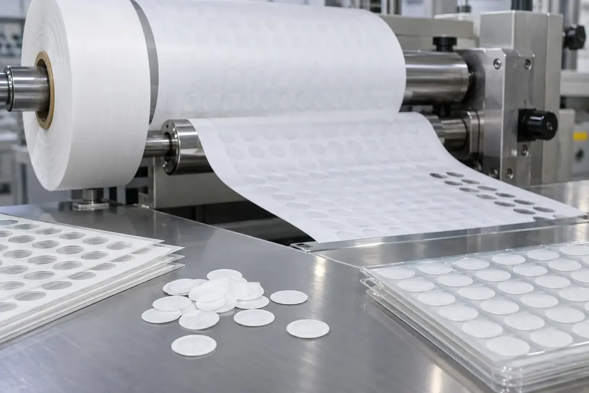
IV-filter PTFE vent membrane die-cutting blades produce small discs or defined vent profiles for fluid-management and air-venting components. Because PTFE membrane may be supplied with a support layer and is sensitive to handling, the review should use the actual construction, approved profile, support method, part-removal sequence, cleanliness criteria and accepted edge sample instead of assuming generic filter-paper behavior.
Updated
Where This Cutting Application Appears
IV-filter vent disc production
PTFE membrane is converted into controlled circular components for integration into infusion-filter assemblies.
Spike-vent profile preparation
Defined membrane shapes are cut to match the approved geometry of a vented medical-device component.
Supported membrane blanking
Membrane and designated support layers are converted together when required by the validated component construction.
Precision Disc Die-Cutting process boundary
Precision disc die-cutting for PTFE vent membrane for IV filters is planned around repeatable full or controlled-depth formation of a defined shape using registered tooling and a managed waste path; it is not straight slitting, simple length separation or narrow edge cleanup.
Precision Disc Die-Cutting setup checkpoint
For PTFE vent membrane for IV filters, confirm finished geometry, clearance or cutting depth, tool-to-anvil support, registration, feed orientation and waste or part release.
Precision Disc Die-Cutting acceptance checkpoint
For PTFE vent membrane for IV filters, evaluate complete geometry, dimensions, registration, burr or fiber pull, corner integrity, waste separation and part flatness.
Define the Required Cut Result
- Complete disc or profile separation without attached membrane strands or torn support.
- Stable geometry matched to the controlled component drawing and inspection method.
- Minimal loose edge fragments and controlled contact with functional membrane surfaces.
- Orderly part removal and collection without folding, mixing or avoidable contamination.
Problems to Diagnose Before Changing the Knife
Membrane disc remains partly connected to the web
- Map the connected location on repeated samples and compare it with feed direction.
- Confirm whether membrane, support or both must be separated at that feature.
- Review local support and part-ejection sequence around the incomplete boundary.
Loose PTFE fragments appear at the perimeter
- Use the customer's normal inspection method to document fragment location and type.
- Compare incoming material edges, newly cut parts and parts after collection.
- Separate cutting debris from contamination introduced by handling equipment.
Thin membrane folds during part removal
- Observe the point at which the part leaves its support or surrounding waste.
- Review pickup, ejection and collection contact with both membrane faces.
- Compare unsupported and carrier-supported handling using representative samples.
Support layer separates at the cut edge
- Identify the supplied layer interface and the location where separation begins.
- Inspect whether separation occurs during cutting, ejection or later transfer.
- Confirm the approved post-cut condition for each layer in the component.
Knife Forms That May Be Considered
| Possible knife form | When it may be considered | What must be confirmed |
|---|---|---|
| Precision flatbed disc-punching die | For sheet-fed or indexed blanking of small PTFE vent discs and simple medical membrane profiles. | Controlled geometry, membrane and support construction, local support, part ejection, collection and accepted edge sample. |
| Rotary membrane blanking die | For repeated PTFE vent components converted continuously from carrier-supported rollstock. | Repeat layout, web path, machine interface, carrier condition, skeleton-waste path and part-transfer method. |
| Kiss-cutting die for carrier-supported membrane | When shaped PTFE components must remain on a designated carrier for later automated assembly. | Carrier identity, required cut result, liner integrity, release direction, pickup method and cleanliness requirement. |
Information to Send for Technical Review
You do not need to know the exact blade name. Send the available workpiece, machine, current-knife and cut-result information so the application can be reviewed against a drawing or sample.
- PTFE membrane identification, support construction and representative production samples.
- Functional face, hydrophobic or treated-side identification supplied by the customer.
- Controlled disc or profile drawing with datum and revision identified.
- Roll or sheet format, repeat layout, feed direction and carrier arrangement.
- Machine station, tooling interface, support, ejection and collection method.
- Accepted and rejected parts showing incomplete cuts, fragments, folds and layer separation.
- Inspection, cleanliness, contact, traceability and packaging requirements.
- Trial quantity, assembly process and current cutting information if available.
Questions About This Cutting Application
Can PTFE vent membrane blades be reviewed as ordinary filter-paper cutters?
No. The membrane construction, support, functional surface, profile and part-handling sequence must be reviewed directly.
Should the support layer be cut with the PTFE membrane?
Only if the controlled component design requires it; document the intended result for each supplied layer.
Why is the part-removal method important?
Small flexible membrane parts may fold, remain attached or collect contamination during ejection and transfer.
What samples should be supplied for review?
Provide uncut membrane, approved parts and rejected parts with both faces and the material direction clearly identified.
Can cleanliness acceptance be assumed from the medical application?
No. The customer should provide the applicable inspection, handling and packaging requirements for the component.
Related product and service information
- Tyvek Sterile Barrier Tray Lid Die-Cutting Blades - Tyvek sterile-barrier tray-lidding material · Registered lid die-cutting
- Microfluidic Diagnostic Adhesive Tape Die-Cutting Blades - Liner-backed microfluidic diagnostic adhesive tape · Registered die-cutting and kiss-cutting
- PCR Microplate Sealing Film Die-Cutting Blades - PCR microplate sealing film · Sheet die-cutting and tab profiling
Request a Custom Cutting-Knife Review
Send the workpiece details, machine or holder information, current knife photos or sample, required quantity and examples of the present cut problem. Final dimensions, material, edge geometry and tolerances are confirmed from the approved requirements.