
Blade Application Guides / Application Guide / Electronics recycling
Flexible Printed Circuit Scrap Primary Shredder Knives
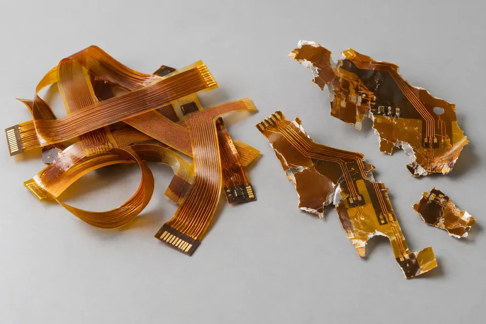
Primary shredding accepts the original flexible-circuit offcut, panel skeleton or ribbon-like feed and prepares a coarse fraction for a named secondary machine. Confirm copper coverage, polymer layer stack, attached components and maximum feed geometry; these features change capture and wrapping behavior. Judge the knife by stable first-stage opening, not by a final granule target.
Updated
Where This Cutting Application Appears
Define the incoming feed
Sort full panels, long ribbons and punched skeletons by size and construction. Record metal coverage, adhesive layers and any attached components. Long strips can behave differently at the hopper than compact pieces; a trial must observe how material enters and whether it bridges or winds around the rotor.
Set the coarse opening objective
Specify an acceptable large-fragment distribution that the next reducer can accept. Compare the discharge with the target by mass or count in agreed size bands. Do not call the first-stage output a finished granule simply because it passed a coarse screen.
Review the cutting interface
Use the machine drawing to identify rotor cutters, counterknife, screen and clearances. Inspect cutting edges and holder fit before a trial. If copper-bearing strips wrap around the rotor, investigate feed length, cutter engagement, clearance and discharge before assuming a harder knife grade is the answer.
Contain the by-products
Observe dust, heat and loose metal-bearing particles at feed and discharge. Confirm the site extraction and housekeeping plan for the actual scrap stream. Keep trial batches traceable by construction so a changed input is not mistaken for a tooling change.
Define the Required Cut Result
- Accept representative incoming flexible-circuit scrap without persistent bridging.
- Produce a coarse fraction suitable for the named secondary machine.
- Limit wrapping and uncut long tails to the agreed inspection limits.
- Record dust, temperature and discharge behavior during a controlled trial.
Problems to Diagnose Before Changing the Knife
Long offcuts wind around the rotor
- Separate ribbon-like feed from compact pieces and record its length.
- Inspect cutter engagement, counterknife condition and the clearance at the wrap point.
- Check whether feed metering or pre-cutting changes the behavior.
The hopper bridges while the rotor is clear
- Measure incoming panel or skeleton dimensions against the feed opening.
- Inspect the feed method and pusher action under load.
- Trial a controlled feed batch rather than increasing speed blindly.
Discharge contains too many intact panels
- Compare the output against the agreed coarse-size bands.
- Check rotor and counterknife condition, screen condition and residence path.
- Confirm that the incoming layer stack did not change between samples.
Dust or heat increases during the run
- Stop and inspect extraction, accumulation and machine load under the site procedure.
- Compare feed rate and edge condition with the accepted trial.
- Review whether the next stage is backing up the discharge.
FPC primary shredding: verify feed capture before judging coarse output
The primary cutter must accept representative original scrap without confusing a hopper or discharge problem with edge selection.
Ribbon-like offcuts wind around the rotor
Separate long ribbons from compact panel pieces, record their length and inspect hook engagement, counterknife condition, anti-wrap clearance and discharge backup.
Panel skeletons bridge before reaching the cutters
Compare maximum panel geometry with the feed opening and pusher action. Trial controlled presentation instead of increasing speed.
Coarse output carries intact panels or excessive dust
Measure agreed coarse bands and inspect screen/residence path, cutter seats and layer-stack variation from the same feed batch.
Acceptance Criteria for a Controlled Trial
Agree how the trial will be judged before changing the knife or machine setting.
- Document panel, skeleton and ribbon proportions plus maximum feed geometry and attached components.
- Count bridging, wrapping, reversal and abnormal-load events over a fixed batch.
- Measure coarse output bands, intact panels and long tails for the next machine’s feed limit.
- Record dust, temperature, discharge behavior and labeled cutter/counterknife edge marks.
Knife Forms That May Be Considered
| Possible knife form | When it may be considered | What must be confirmed |
|---|---|---|
| Shredder rotor cutter | For first-stage capture and opening when the installed shredder uses replaceable rotor cutters. Review the hooked rotor cutter and counterknife as a first-stage capture interface; confirm tooth profile, holder seat, fastener, direction and anti-wrap clearance from the machine drawing. | Confirm tooth profile, holder seat, fastener and rotation from the OEM drawing. |
| Stationary counterknife | As the fixed mating edge in a compatible primary shredder. | Confirm its mounting, edge position and service clearance with the rotor drawing. |
Information to Send for Technical Review
You do not need to know the exact blade name. Send the available workpiece, machine, current-knife and cut-result information so the application can be reviewed against a drawing or sample.
- Incoming FPC offcut forms, maximum panel/ribbon dimensions and representative batch mix
- Layer stack, copper coverage, adhesive and attached-component description
- Moisture, oil, solder, connector and other hard-inclusion controls
- Required coarse output bands and the named secondary machine feed limit
- Primary shredder make or model, shaft arrangement, rotation and feed method
- Rotor cutter, counterknife, holder, spacer and screen drawings with used samples
- Feed rate, reversals, wrapping locations, load, dust and temperature records
- Accepted and rejected coarse samples from the same traceable batch
Related Recycling Knife and Service Pages
Questions About This Cutting Application
Is primary shredding intended to make the final fine fraction?
No. This stage opens the feed and makes coarse fragments for the next specified operation. Record the downstream reducer and its feed limit.
Can flexible-circuit scrap be treated as pure copper foil?
No. Copper-clad polyimide is one possible construction, but actual waste may include other layers and components. Obtain a sample and layer description.
What matters most when long ribbons are fed?
Observe bridging and wrapping as well as fragment size. The feed geometry and rotor engagement are part of the trial.
Does a smaller screen always solve oversize?
No. Screen, cutting condition, residence, feed rate and machine load interact. Confirm any screen change with the machine owner.
What should the RFQ include?
Include actual scrap samples, a machine drawing, feed geometry, coarse output limits and records of current wrap or dust problems.
Public references and scope
These public sources provide material, cutting-method or safety context for this guide. Supplier pages describe their own materials or equipment; they do not establish a MEIRENTE blade specification or performance claim. Confirm the actual grade, machine setup and required cut with a drawing or sample.
Related product and service information
- Flexible Printed Circuit Scrap Secondary Shredder Knives - flexible printed circuit scrap · secondary shredding
- Lithium Battery Separator Scrap Primary Shredder Knives - lithium battery separator scrap · primary shredding
- Mixed Copper Cable Scrap Primary Shredder Knives - mixed copper cable scrap · primary shredding
Request a Custom Cutting-Knife Review
Send the workpiece details, machine or holder information, current knife photos or sample, required quantity and examples of the present cut problem. Final dimensions, material, edge geometry and tolerances are confirmed from the approved requirements.