
Blade Application Guides / Application Guide / PEM electrolyzer membrane electrode assembly manufacturing
PEM Electrolyzer Catalyst-Coated Membrane Die-Cutting Blades
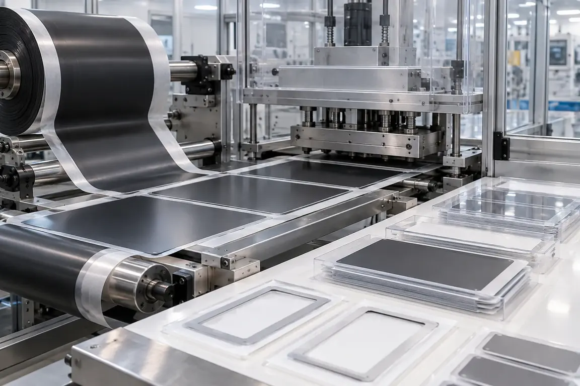
PEM electrolyzer catalyst-coated membrane die-cutting blades prepare registered membrane profiles from material that already carries functional catalyst layers. This is different from width slitting an uncoated membrane roll: the review must protect coated areas, define active-area and sealing-boundary relationships, identify any carrier or cover layer, control waste contact and use the customer's approved component and inspection method as the reference.
Updated
Where This Cutting Application Appears
Registered CCM outline preparation
The coated membrane is cut to an approved outer geometry while its relationship to the active area is maintained.
Assembly opening preparation
Specified openings or alignment features are produced without unnecessary contact with the functional catalyst-coated region.
Carrier-supported component conversion
CCM material is cut on its designated carrier or support for controlled removal, inspection and later assembly.
Registered Profile Die-Cutting process boundary
Registered profile die-cutting for PEM electrolyzer catalyst-coated membrane is planned around repeatable full or controlled-depth formation of a defined shape using registered tooling and a managed waste path; it is not straight slitting, simple length separation or narrow edge cleanup.
Registered Profile Die-Cutting setup checkpoint
For PEM electrolyzer catalyst-coated membrane, confirm finished geometry, clearance or cutting depth, tool-to-anvil support, registration, feed orientation and waste or part release.
Registered Profile Die-Cutting acceptance checkpoint
For PEM electrolyzer catalyst-coated membrane, evaluate complete geometry, dimensions, registration, burr or fiber pull, corner integrity, waste separation and part flatness.
Define the Required Cut Result
- Registered finished geometry matched to the controlled CCM or assembly drawing.
- Clean membrane edges without loose fragments, extended tears or attached waste.
- Protected catalyst-coated surfaces with controlled contact and particle transfer.
- Stable part and waste removal without stretching or shifting the usable CCM.
Problems to Diagnose Before Changing the Knife
Catalyst layer flakes or transfers near the cut
- Identify coated areas and their position relative to every planned cut boundary.
- Inspect both sides using the customer's normal method and compare accepted samples.
- Review material contact before, during and after cutting to separate cutting damage from handling transfer.
Finished profile is misregistered to the active area
- Confirm the datum, image, sensor mark or mechanical reference used in production.
- Measure the profile and coated-area relationship on the same finished component.
- Record whether drift is progressive, intermittent or associated with web or sheet movement.
Membrane wrinkles or stretches around a feature
- Document support and hold-down conditions around the affected edge or opening.
- Determine whether deformation begins during cutting, release or part transfer.
- Compare the finished part in its supported and customer-defined inspection condition.
Waste contacts the coated surface during removal
- Map waste pieces and the direction in which each one is removed.
- Observe corners and narrow connections that alter the waste path.
- Review collection and transfer steps for secondary contact with usable components.
Knife Forms That May Be Considered
| Possible knife form | When it may be considered | What must be confirmed |
|---|---|---|
| Registered flat profile die-cutting arrangement | For sheet-fed or indexed CCM material requiring coordinated outlines and openings. | Controlled drawing, active-area reference, layer stack, support, waste sequence and accepted component sample. |
| Rotary registered die-cutting arrangement | For repeated CCM profiles converted from a moving web on compatible production equipment. | Repeat layout, registration method, web path, machine interface, carrier route and inspection reference. |
| Carrier-supported profile cutting arrangement | When the membrane requires a retained support layer during cutting, removal or transfer. | Layer order, intended cut result by layer, carrier integrity, peel direction and assembly transfer method. |
Information to Send for Technical Review
You do not need to know the exact blade name. Send the available workpiece, machine, current-knife and cut-result information so the application can be reviewed against a drawing or sample.
- CCM product description and representative material in the intended supplied condition.
- Identification of coated regions, functional sides, carriers and protective layers.
- Controlled finished-profile drawing with active-area datum and revision.
- Roll or sheet format, material orientation and registration reference.
- Machine station, support, tooling interface and waste-removal arrangement.
- Accepted and rejected parts showing coating edges, cut boundaries and openings.
- Customer inspection, cleanliness, contact, storage and packaging requirements.
- Trial quantity, production sequence and current cutting information if available.
Questions About This Cutting Application
How is CCM die-cutting different from PEM roll slitting?
CCM cutting must register finished features to existing functional catalyst-coated areas and protect those surfaces during conversion.
Can the catalyst boundary be estimated from an overall sheet photograph?
No. Use a controlled drawing, defined datum and clearly identified material or inspection reference.
Should cover layers and carriers remain on trial material?
Use the intended production stack and define which layers must be cut, retained, peeled or transferred.
What should a rejected CCM sample show?
Mark orientation, active area, cut boundary and any coating loss, wrinkles, tears, particles or waste contact.
Why is waste removal included in the review?
Released waste can touch, stretch or contaminate the coated membrane even when the initial cut is complete.
Related product and service information
- PEM Electrolyzer Titanium PTL Cutting Blades - PEM electrolyzer titanium porous transport layer · Sheet sizing, profile cutting and edge trimming
- Lithium Battery Electrode Tab Notching Blades - Coated lithium battery electrode web · Electrode tab notching
- Fuel Cell Subgasket Film Die-Cutting Blades - Fuel cell subgasket film laminate · Registered die-cutting and kiss-cutting
Request a Custom Cutting-Knife Review
Send the workpiece details, machine or holder information, current knife photos or sample, required quantity and examples of the present cut problem. Final dimensions, material, edge geometry and tolerances are confirmed from the approved requirements.